
Oscillator using crystal
More: The single transistor circuit produces more of a ramping waveform but the output swings the full supply voltage range so it will easily drive the input to a CMOS binary counter.
The circuits designed to generate a 32.768 KHz square wave from a watch crystal utilize two distinct configurations: one based on a 4069 inverter and the other utilizing a single transistor. The 32.768 KHz frequency is commonly used in timekeeping applications, particularly in wristwatches, due to its suitability for division down to a 1 Hz signal.
In the first configuration, the 4069 inverter is employed as an oscillator. This IC contains six inverters that can be used in a feedback loop with the watch crystal to create a stable oscillation. The crystal's inherent frequency determines the oscillation rate, and the inverter amplifies the signal to produce a clean square wave output. The output from this circuit can drive a 15-stage binary counter, resulting in a 1-second pulse when the output is divided down. This configuration is favored for its ability to produce a sharp and well-defined waveform, which is essential for accurate timing applications.
In contrast, the second configuration utilizes a single transistor as an oscillator. While this circuit can generate the required frequency, it typically produces a ramping waveform rather than a true square wave. This ramping output, however, has the advantage of swinging across the full supply voltage range, making it capable of directly driving the inputs of CMOS binary counters without additional amplification. Despite its simplicity and effectiveness in certain applications, the output's less-than-ideal waveform may lead to timing inaccuracies when used in precision applications.
Both circuits effectively generate the desired frequency and can be adapted for various applications, but the choice between them should consider the requirements for waveform integrity and output characteristics. The 4069 inverter circuit is recommended for applications demanding precise timing, while the transistor circuit may suffice for less critical uses where full supply voltage swings are acceptable.Below are a couple circuits you can use to produce a 32.768 KHz square wave from a common watch crystal. The output can be fed to a 15 stage binary counter to obtain a 1 second square wave. The circuit on the left using the 4069 inverter is recommended over the transistor circuit and produces a better waveform.
The single transistor circuit produces more of a ramping waveform but the output swings the full supply voltage range so it will easily drive the input to a CMOS binary counter. 🔗 External reference
Related Circuits
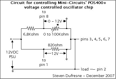
This is a UHF oscillator circuit designed to utilize the Mini-Circuits POS-400+ voltage-controlled oscillator chip. By applying a voltage between 0 to 12V on pin 8, it produces a sine wave output ranging from 200MHz to 380MHz on pin...
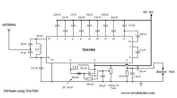
A simple FM radio circuit with a diagram and schematic using the IC TDA 7000. This low-cost single-chip FM radio circuit design is easy to assemble and is suitable for creating a portable FM radio. The FM radio circuit utilizing...
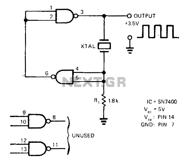
A SN7400 quartz crystal and a resistor provide a square-wave output of approximately 3.5 V. The circuit operates reliably at frequencies from 120 kHz to 4 MHz. The circuit utilizes a SN7400 integrated circuit, which is a quad two-input NAND...
The 2N4416 JFET exhibits very low harmonic distortion, making it ideal for smooth oscillation in electronic circuits. It is particularly effective in applications where minimal harmonic content is essential for high-performance mixer circuits. Below is the circuit diagram of...
This is a voltage controller oscillator that was designed as a wide range oscillator to generate clock pulses for a stepper motor drive system. It does however have some interesting features. The original application used a stepper motor for...
This circuit is a signal line so that you reinforce with a small speaker can control. The LM 386 is a number of versions available. LM 386N-1 can provide a power of 325 mW, the LM-386N 2500 mW, the...
Warning: include(partials/cookie-banner.php): Failed to open stream: Permission denied in /var/www/html/nextgr/view-circuit.php on line 713
Warning: include(): Failed opening 'partials/cookie-banner.php' for inclusion (include_path='.:/usr/share/php') in /var/www/html/nextgr/view-circuit.php on line 713