
Low Distortion Oscillator
The 2N4416 JFET (Junction Field Effect Transistor) is a popular choice in oscillator designs due to its favorable characteristics, including low noise and low distortion. In a Low Distortion Oscillator circuit, the 2N4416 can be configured as a common source amplifier, which allows for the generation of stable oscillations with minimal harmonic interference.
Typically, the circuit consists of the 2N4416, resistors, capacitors, and an inductor, arranged to form a feedback loop. The feedback network is designed to set the frequency of oscillation, while ensuring that the output signal remains clean and free from unwanted harmonics. The choice of passive components is critical; for instance, using high-quality capacitors can further reduce noise and distortion.
The power supply for the circuit should be stable, as fluctuations can introduce additional distortion. A bypass capacitor may be included to filter out any high-frequency noise from the power supply. Additionally, the layout of the circuit board should be carefully considered to minimize parasitic capacitance and inductance, which can affect performance.
In applications such as RF mixers, the low harmonic distortion provided by the 2N4416 ensures that the output signal retains its integrity, allowing for better signal processing and improved overall system performance. The circuit can be tuned for various frequencies by adjusting the values of the reactive components, making it versatile for different applications in communications and signal processing.With very low harmonic distortion, 2N4416 JFET is suitable to smoothly oscillate in a circuit. On application where low harmonic content is required for a good mixer circuit, JFET local oscillator is very good. Below is the circuit diagram of Low Distortion Oscillator: 🔗 External reference
Related Circuits

This circuit is designed to be housed in a compact plastic or preferably metal enclosure, powered by a 9V battery. It features a level control, a male XLR connector (similar to those used in microphones), and a switch. The...
This circuit incorporates heavy degenerative feedback, utilizing a small lamp as a nonlinear compensating resistance. It provides a constant output frequency and voltage for supply voltages ranging from 12 to 32 V, and operates effectively at temperatures as low...
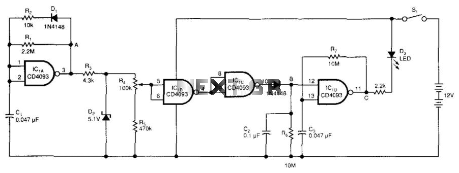
The low-voltage battery detector employs a CD4093 Schmitt trigger alongside a capacitor functioning as a 1-bit dynamic RAM. The circuit is designed to conserve power through a periodic testing method. Components IC1A, CI, R1, R2, and D1 produce a...
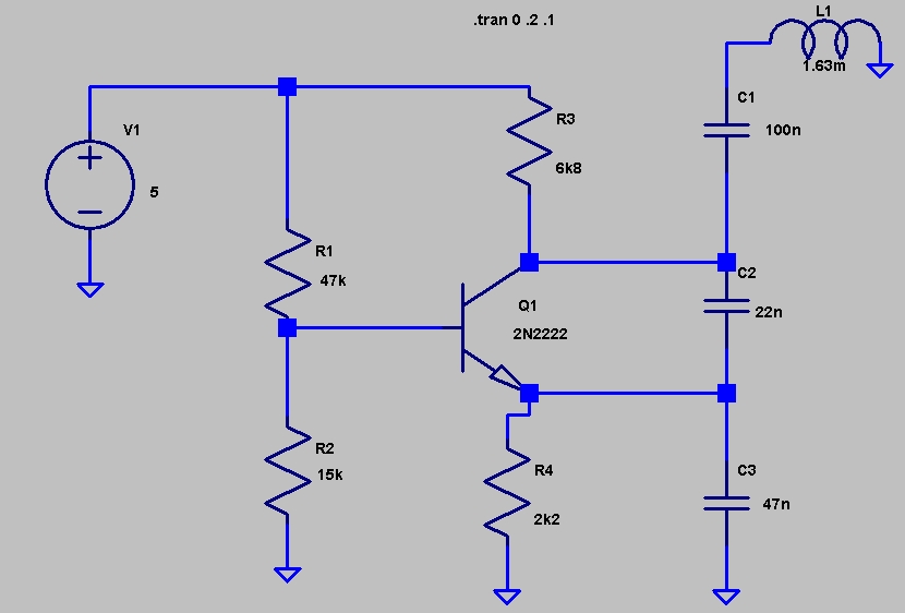
This circuit was featured in the "design ideas" section of EDN's March 5, 2007 issue. It is a relatively simple circuit that allows investigation into how the inductance of a toroid (or any core) is affected by saturation, which...
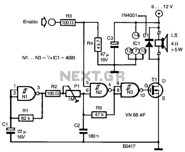
A CD4093 chip and several components form a siren oscillator that drives power MOSFET Tl. A speaker is directly powered by this device. The siren is activated by a logic high signal applied to the ENABLE input. The circuit comprises...
The hysteresis characteristic indicates that the voltage level transitions to high (H) when the input voltage of the inverter rises from 0 V, and the voltage level transitions to low (L) when the input voltage descends from +5 V....