
Single Chip FM Radio Circuit with Diagram using TDA 7000 IC
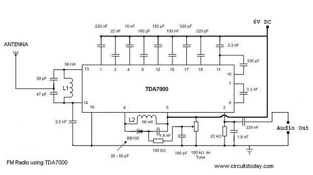
The FM radio circuit utilizing the TDA 7000 integrated circuit (IC) is designed for simplicity and affordability while providing reliable FM reception. The TDA 7000 is a highly integrated FM receiver IC that combines all essential functions required for FM radio operation, including RF amplification, demodulation, and audio output.
The circuit typically includes the following components: the TDA 7000 IC, a few passive components such as resistors and capacitors, an antenna for signal reception, and a speaker or headphone jack for audio output. The power supply for the circuit can be provided by batteries or a DC power source, ensuring portability.
The schematic diagram illustrates the connections between these components. The antenna is connected to the input of the TDA 7000, which amplifies the incoming RF signals. The demodulator within the IC converts the modulated signals back into audio signals. These audio signals are then sent to an output stage, which drives the speaker or headphone.
The tuning of the radio can be achieved by adjusting the values of certain capacitors and inductors in the circuit, allowing users to select different FM stations. The design is compact, making it suitable for integration into portable radio enclosures. Overall, this circuit design serves as an excellent introduction to FM radio technology and is suitable for hobbyists and educational purposes.A simple FM Radio circuit with diagram and schematic using IC TDA 7000. This low cost single chip fm radio circuit design is easy to make and is suitable to make a FM portable radio.. 🔗 External reference
Related Circuits
Various tools can be utilized with a musical instrument to generate different sound effects, with the simplest being the repetition of tone, often referred to as echo. This equipment enhances the music being played. The circuit diagram is designed...
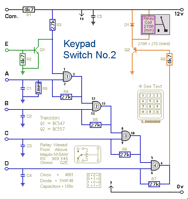
This is a simplified version of the 4-Digit Keypad Controlled Switch. The design has been modified to reduce the complexity of the circuit and the number of components required. Consequently, the code may be somewhat less secure; however, it...
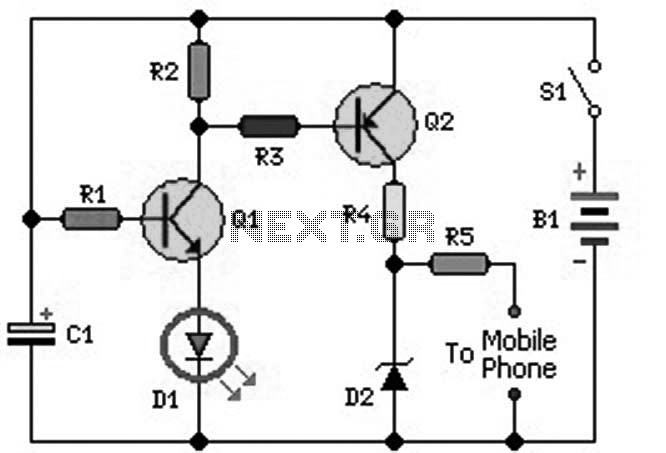
An ideal mobile charger utilizing 1.5-volt pen cells to charge mobile phones while traveling. This charger can replenish a cell phone battery three to four times in locations where AC power is unavailable. Most mobile phone batteries are rated...
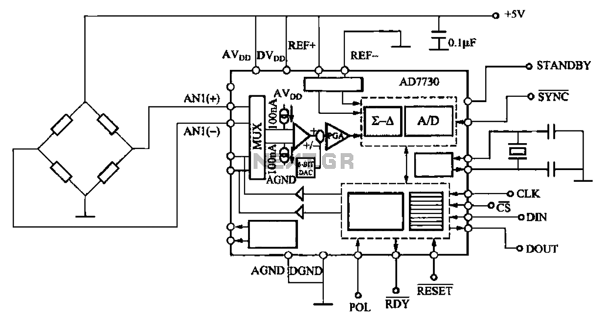
AD7710/7715/7730 multifunction digital sensor signal conditioning integrated circuits (ICs) that combine a digital interface with a control port, a clock generator, a digital filter, amplitude modulation, a programmable gain amplifier, an analog-to-digital (A/D) converter, and additional electrical pathways. The...
This is a circuit which I originally included in my book, 22 Tested Transistor Projects, published by Babani Press in 1976 (ISBN 0 900162 63 S). It is one I had great fun with. It uses the PUT Complimentary...
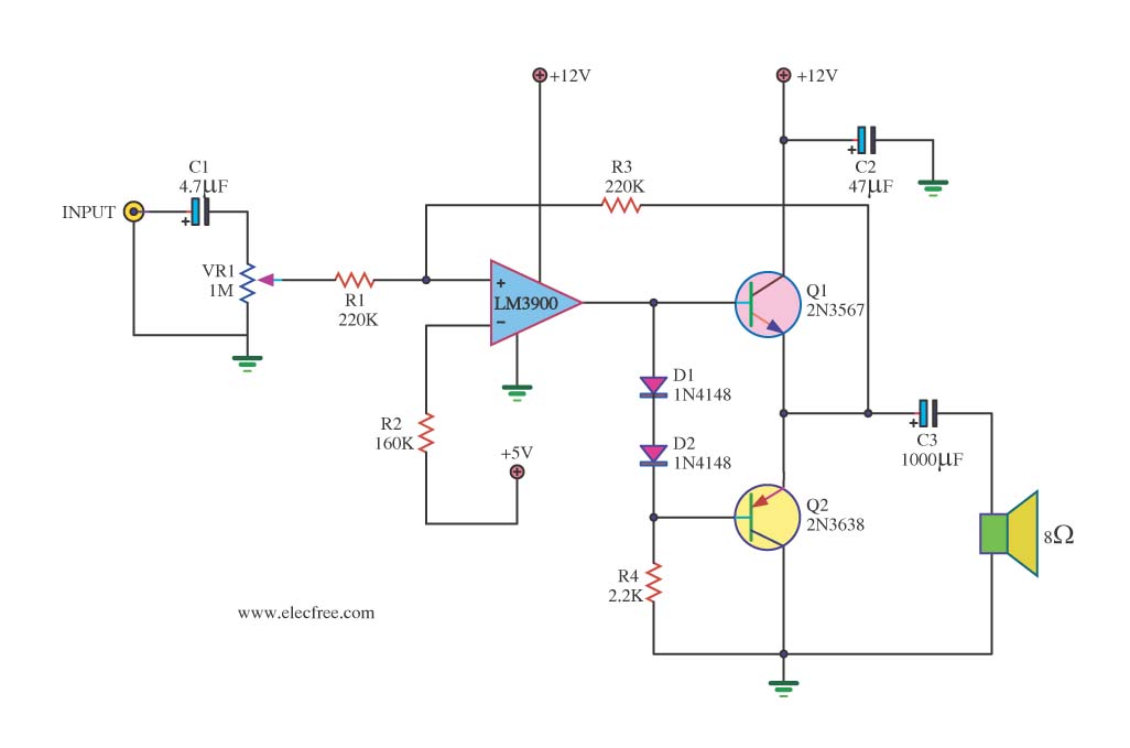
This is a mini-sized power amplifier rated at 2 watts OTL that utilizes the LM380 integrated circuit. It serves as a ready-made circuit for audio applications and communication, requiring minimal external equipment. The capacitor C6 can be selected from...
Warning: include(partials/cookie-banner.php): Failed to open stream: Permission denied in /var/www/html/nextgr/view-circuit.php on line 713
Warning: include(): Failed opening 'partials/cookie-banner.php' for inclusion (include_path='.:/usr/share/php') in /var/www/html/nextgr/view-circuit.php on line 713