
555 astable multivibrator circuit diagram
The 555 timer is a versatile integrated circuit commonly used in various applications, including timing, pulse generation, and oscillation. In astable mode, the 555 timer continuously switches between its high and low states, generating a square wave output. This mode is characterized by the absence of a stable state, making it ideal for applications such as clock pulses for digital circuits or LED flashing.
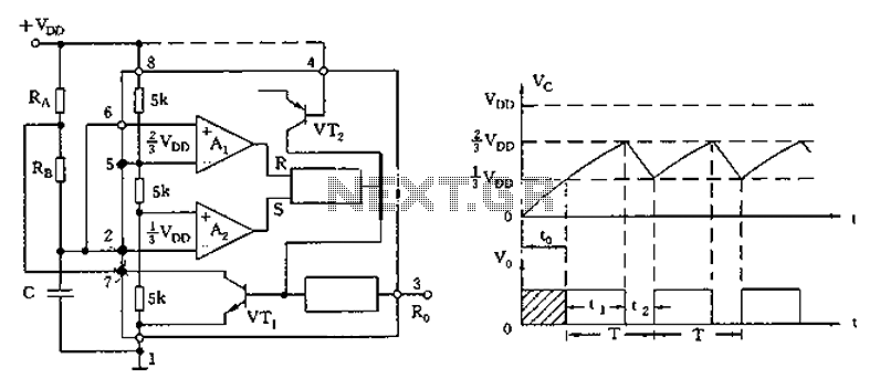
The configuration involves connecting two resistors (R1 and R2) and a capacitor (C) to the 555 timer. The resistors determine the charge and discharge times of the capacitor, which in turn sets the frequency and duty cycle of the output waveform. The output frequency (f) can be calculated using the formula:
\[ f = \frac{1.44}{(R1 + 2R2)C} \]
The duty cycle (D) is given by:
\[ D = \frac{R2}{R1 + 2R2} \]
In one-shot mode, the 555 timer generates a single pulse when triggered. In this case, the trigger input on pin 2 is connected to the charge and discharge circuit of capacitor C, allowing the capacitor to control the timing interval for the output pulse. The duration of the output pulse is determined by the resistor (R) connected to the discharge pin (pin 7) and the capacitor (C) connected to the threshold pin (pin 6). The pulse width (T) can be calculated as:
\[ T = 1.1 \times R \times C \]
This configuration allows for precise control over timing applications without the need for external triggering mechanisms, making it suitable for various electronic projects, including timers, pulse-width modulation, and frequency generation.As illustrated, the 555 (or 556 1/2) and three resistive, capacitive element connected as shown, constitute astable multivibrator mode. And one-shot mode except that only the t rigger terminal (pin 2) connected to the charge and discharge circuit C, rather than by external trigger control.
Related Circuits
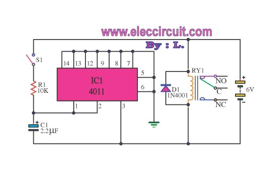
This circuit illustrates the use of the 4011 integrated circuit (IC) for a surge protection electronic circuit diagram. Features include the ability to delay the activation of other appliances connected to the output. The 4011 IC is a quad 2-input...
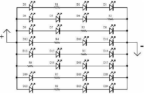
A light-emitting diode (LED) lamp is a solid-state lighting device that utilizes light-emitting diodes as its light source. LEDs are a cost-effective and convenient choice for various lighting applications. They are available in an extensive range of colors, styles,...

This tracking transmitter consists of four distinct subassemblies: a free-running multivibrator, a transmit switch, an audio-tone generator, and an FM transmitter. The multivibrator, which produces a pulse width with a pulse separation of 1500 ms, is built around Q1...
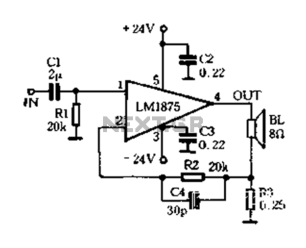
A current-sense amplifier is utilized to enhance the performance of the LM1875 current-mode amplifier circuit, as depicted in Figure 5-20. The resistor R3 and the series resistance of the speaker contribute to the current flowing through R3. This current...
This precise one-pulse-per-second clock is constructed using a few common components and is driven by a 50 or 60 Hertz mains supply without a direct connection to it. An audible beep or a metronome-like click, along with a visible...
This is a straightforward liquid detector that utilizes a relay to activate an evacuation mechanism. It can be employed for water or any liquid that conducts electricity. Any PNP transistor capable of handling the relay current can be used....