
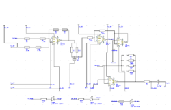
Double astable multivibrator circuit diagram

The schematic involves a 556 timer IC, which is essentially two 555 timer circuits integrated into a single package. Each half of the 556 timer can be configured as either an astable or monostable multivibrator. In the astable configuration, the circuit continuously oscillates, producing a square wave output. The frequency of oscillation is determined by the values of the resistors and capacitors connected to the timer.
In this configuration, the capacitors C1, C2, and C3 are used to set the timing intervals. By selecting equal values for these capacitors, the circuit ensures that both multivibrators operate in sync, producing clock signals that maintain a consistent phase relationship. The resistors connected to the timing capacitors also play a crucial role in defining the duty cycle and frequency of the output signals.
The output from each multivibrator can be utilized for various applications, such as clock signals for digital circuits, timing applications, or generating pulse-width modulation (PWM) signals. The ability to adjust the time constant by varying the resistor values allows for a wide range of frequencies to be generated, making this circuit versatile for different electronic applications.
Overall, the dual time base circuit utilizing the 556 timer provides a robust solution for generating synchronized clock signals with adjustable frequencies, making it suitable for use in various electronic systems where timing and synchronization are critical.As shown, the circuit consists of a dual time base circuit 556 consisting of two synchronized multivibrator, two output clock signal synchronized intervals and the oscillation frequency can be varied by adjusting the time constant, flexible and convenient . When you select C1 = C2 = C3, the oscillation frequency
Related Circuits
This circuit utilizes a JFET to receive signals from an LED and buffer them. The output voltage is managed using an IC 1458 or LM1458, which provides approximately 7 volts in darkness and experiences a drop of about 2...
This week involved the completion of several objectives. Initially, software was downloaded to design the schematic for a circuit intended for translation onto a PCB. A significant portion of the week was dedicated to tutorials and familiarization with the...
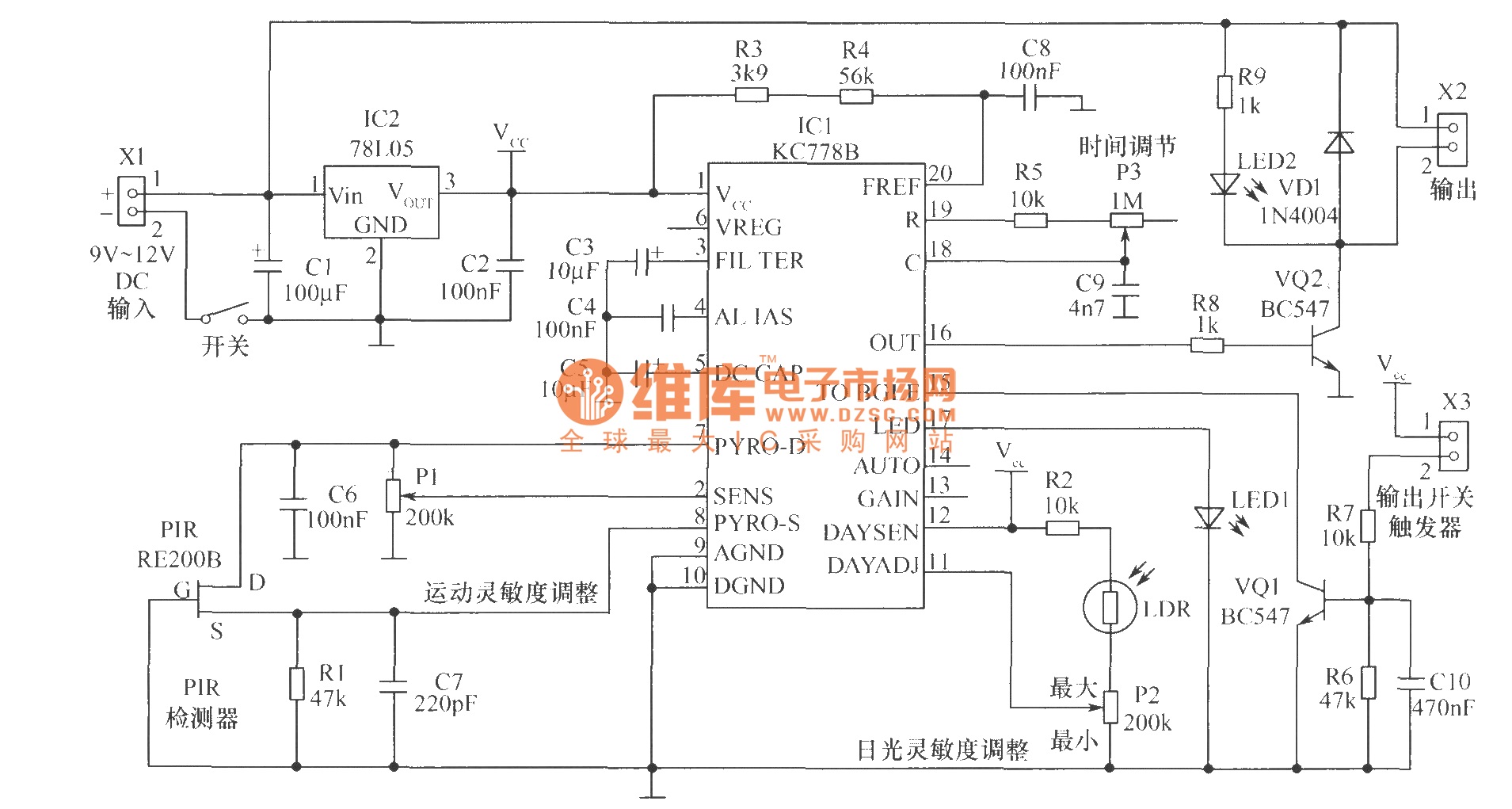
The core component of the motion detection circuit is the motion detection chip IC1 (KC778B). The signal frequency from the PIR sensor is low, ranging from 0.1Hz to 10Hz, while the bandwidth is quite broad, which the chip will...
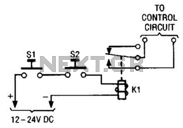
The simple two-hand safety control switch consists of two pushbutton switches connected in series; both must be depressed to energize the relay. The two-hand safety control switch is designed to enhance safety in applications where the operation of machinery or...
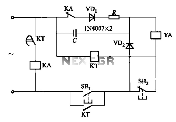
AC solenoid DC circuit operation operates similarly to a DC contactor circuit, but the AC solenoid pull circuit is illustrated in the provided figure. The capacitance C is generally between 1-10 microfarads (µF), with a minimum of 20 microfarads...
This circuit functions with inaudible (ultrasonic) sound. Sound of frequency up to 20 kHz is audible to human beings. The sound of frequency above 20 kHz is called ultrasonic sound. The circuit described generates (transmits) ultrasonic sound of frequency...