
Oscilloscope AC Probe
The low frequency corner is a function of the inductance of the secondary and the total resistance across the secondary. The total resistance is the sum of the resistance of the secondary winding (Rwire below) and the termination resistance. The effects of the 1K pot and the connection to the oscilloscope are ignored. The toroid is held in place by a couple of plastic wire ties (Panduit brand tie-wraps to be precise) and inserted a length of vinyl insulation stripped off of a piece of multiconductor cable through the hole in the toroid and the hole in the circuit board. The termination resistor and the calibration pot are mounted on the circuit board, their leads bent over and soldered to each other and the leads from the transformer. The other probe used the barrel from a BIC ballpoint pen as the insulated sleeve, but this was rigid and not very forgiving of mechanical misalignment of the holes, thus the use of vinyl in this one.
The shielded cable with the BNC connector on it was fastened to the circuit board, the vinyl sleeve was installed, and the board was fastened into the box with a few dabs of hot melt glue. After calibration, the cover was fastened into place with the screws and the probe was ready to go. The secondary of one probe was wound with #30 wire magnet wire and the secondary of the other was wound with #30 Kynar insulated wire wrapping wire. A larger wire diameter would mean better low frequency response, but it would have also induced more high frequency losses because of eddy currents resulting from the flux gradient from the core across the conductor.
This current probe is designed to operate effectively in a frequency range from a few tens of Hertz up to a couple of megahertz, accommodating current measurements from several tens of milliamps to a maximum of approximately 10 amps peak-to-peak. The operational principle involves passing the wire carrying the current through a toroidal core, which serves as a sensing element. The probe's output voltage is proportional to the input current, allowing for direct observation of the current waveform on an oscilloscope.
To enhance sensitivity, the design allows for multiple turns of the current-carrying wire through the toroid. This method increases the inductance and, consequently, the output voltage for a given current, allowing for greater measurement precision without necessitating a complete redesign of the probe. The low-frequency corner frequency is a critical parameter, as it indicates the frequency beyond which the probe maintains its specified sensitivity. Below this frequency, sensitivity diminishes at a rate of -6 dB per octave, necessitating careful consideration of the inductance and resistance in the secondary circuit.
The assembly of the probe includes a toroidal inductor secured with plastic ties, ensuring stability and alignment. The circuit board hosts the termination resistor and calibration potentiometer, which are crucial for fine-tuning the probe's output characteristics. The use of a flexible vinyl sleeve allows for mechanical tolerance during assembly, improving reliability compared to rigid alternatives.
In terms of construction materials, the secondary windings utilize #30 wire, with different insulation types affecting performance. The choice of wire gauge impacts both low-frequency response and high-frequency losses, necessitating a balance between sensitivity and bandwidth. The final assembly is completed with a BNC connector for oscilloscope interfacing, ensuring a secure and reliable connection for accurate measurements.The probe described here was designed to be used over the range of several tens of Hz to a couple MHz with currents from a few tens of milliamps to about 10 amps peak-to-peak. Formulae are give which will allow you to create a design suitable for your own applications. To use this probe, a wire is connected in series with the load that you want to see the current through, and that wire is passed through the hole in the probe.
An oscilloscope is used to view and measure the current waveform, which is calibrated in terms of volts output per amp of input current. The sensitivty of the circuit can be multipled by using multiple turns in the sensing winding. For example, to get 5 times the sensitivity, pass the input wire through the hole in the toroid five times. Of cousre, it would be much better to design the probe to have the sensitivity required for your application, but this trick is ok if you don't have to do it too often.
After scale factor, the low frequency corner frequency is the next most important consideration. At this frequency, sensitivity is -3 db (-30%) from what it was at significantly higher frequencies, and below this frequency the sensitivity is cut in half every time the frequency is halved, which in other words, is -6 db per octave. The low frequency corner is a function of the inductance of the secondary and the total resistance across the secondary.
The total resistance is the sum of the resistance of the secondary winding (Rwire below) and the termination resistance. We will ignore the effects of the 1K pot and the connection to the oscilloscope. The toroid is held in place by a couple of plastic wire ties (Panduit brand tie-wraps to be precise) and inserted a length of vinyl insulation I stripped off of a piece of multiconductor cable though the hole in the toroid and the hole in the circuit board.
The termination resistor and the calibration pot are mounted on the circuit board, their leads bent over and soldered to each other and the leads from the transformer. The other probe used the barrel from a BIC ballpoint pen as the insulted sleeve, but this was rigid and not very forgiving of mechanical misalignment of the holes, thus the use of vinyl in this one.
The shielded cable with the BNC connector on it was fastened to the circuit board, the vinyl sleeve was installed, and the board was fastened into the box with a few dabs of hot melt glue. After calibration, the cover was fastened into place with the screws and the probe was ready to go. The secondary of one probe was wound with #30 wire magnet wire and the secondary of the other was wound with #30 Kynar insulated wire wrapping wire.
A larger wire diameter would mean better low frequency response, but at the would have also induced more high frequency losses because of eddy currents resulting from the flux gradient from the core across the conductor. 🔗 External reference
Related Circuits
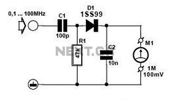
Comprehensive information about RF Probe Circuits is available. Users can learn about and download RF Probe Circuit designs online. RF Probe Circuits are essential tools for testing and analyzing radio frequency signals in various applications, including telecommunications, broadcasting, and electronic...
This circuit functions as a stable frequency counter with an accuracy of 5 significant digits. It operates within a frequency range of 0 to 30 MHz and requires an input sensitivity greater than 100 mV. The probe connects to...
A digital storage oscilloscope (DSO) is a very important piece of test equipment that can do the jobs that a normal CRO just can't handle. Such as capturing single shot and widely spaced waveshapes, and looking at non-repetitive signals...
The Xminilab-B oscilloscope is based on the Atmel AVR ATXMEGA32A4 microcontroller. It is designed as a debug board by the Gabotronis company, as noted on rlocman.ru. The Xminilab-B oscilloscope features a compact and efficient design that leverages the capabilities of...
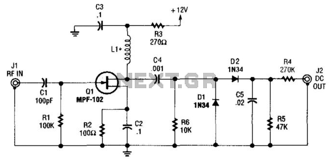
An MFP102 FET is utilized as a wideband amplifier. It can operate with an inductance (LI) of 100 µH for frequencies between 30 to 100 MHz or 1000 µH for frequencies between 2 to 30 MHz. For low frequencies...
The high voltage section of the CRT is unchanged from the original vacuum tube oscilloscope used as the basis of this design. The CRT requires shielding from the main power transformer. Cold roll steel around the CRT does not...