comp probe circuit
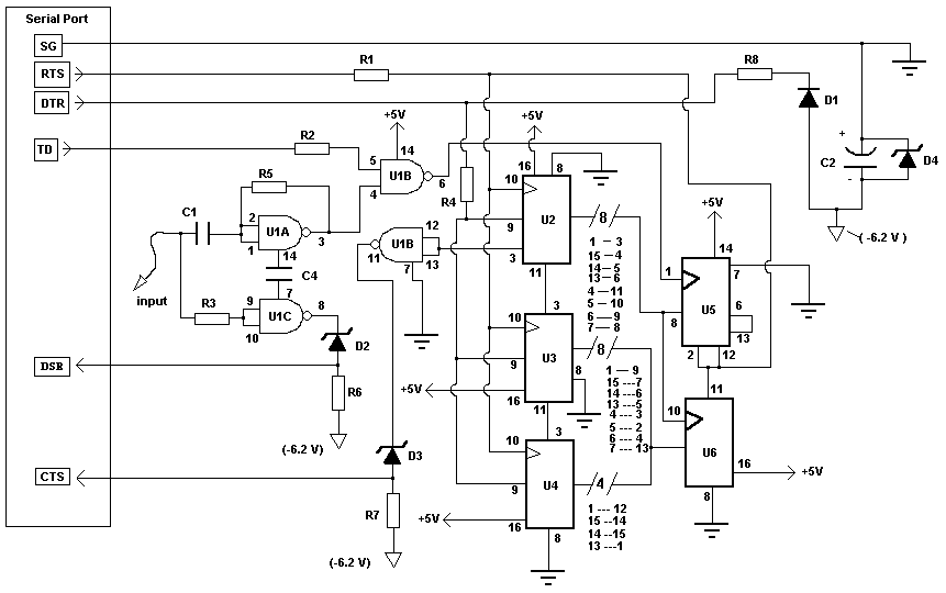
This circuit functions as a stable frequency counter with an accuracy of 5 significant digits. It operates within a frequency range of 0 to 30 MHz and requires an input sensitivity greater than 100 mV. The probe connects to a PC's serial port, utilizing the crystal oscillator already present on the PC's serial card for minimal external circuitry. Additionally, the probe can serve as a logic probe or analyzer with the included software (LPROBE92.EXE). This software is compatible with Intel x86 platforms and operates under DOS, Windows 95, Windows 98, and Windows Me, but it is not functional on NT-based Windows versions, including Windows NT 3.51, Windows NT 4, Windows 2000, Windows 2003, Windows XP, and Windows Vista due to restrictions on direct hardware access. The calibration program, SETPROBE.EXE, is essential for accurate readings, requiring calibration to the specific PC. This program calculates a constant error correction factor for the serial card used with the probe. To determine this correction factor, a reliable oscillator with a known frequency (e.g., a 2 MHz crystal oscillator) is necessary. When CALIBRAT.EXE is executed, the probe samples the frequency and prompts the user to input the true frequency in Hz with 1 Hz accuracy, avoiding decimal points. The calculated correction factor is then stored in PROBE.DAT. Calibration is a one-time requirement. LPROBE92.EXE functions as the logic analysis program, displaying logic states in real-time and allowing sampling speed adjustments via the left and right arrow keys. FPROBE92.EXE serves as the frequency counter program, displaying the measured frequency in Hz, with commas indicating KHz and MHz. To exit FPROBE, any key can be pressed.
This frequency counter circuit is designed for high precision and ease of use, making it suitable for various applications in electronics testing and analysis. The core functionality is based on a microcontroller or dedicated frequency counter IC that processes the incoming signal from the probe. The circuit includes a voltage divider or amplifier stage to ensure that the input signal meets the required sensitivity threshold of greater than 100 mV.
The connection to the PC's serial port is typically achieved through a standard RS-232 interface, which may involve level shifting to ensure compatibility with the logic levels of the PC. The software provided with the system, including LPROBE92.EXE and SETPROBE.EXE, plays a critical role in the overall functionality. These programs facilitate the calibration process and provide real-time data analysis capabilities.
The calibration process is crucial for maintaining accuracy. By using a known reference frequency, the user can input the precise frequency into the calibration software, which then computes the necessary correction factor. This factor compensates for any discrepancies in the crystal oscillator used in the PC's serial card, ensuring that the frequency readings are reliable and accurate.
The logic analysis feature allows users to observe digital signals in real time, making it a valuable tool for debugging and testing digital circuits. The ability to adjust the sampling speed enhances the flexibility of the analysis, allowing users to capture fast-changing signals effectively.
Overall, this circuit design and accompanying software provide a robust solution for frequency measurement and logic analysis, catering to the needs of electronics engineers and hobbyists alike.This circuit is a stable frequency counter accurate to 5 significant digits. The range is 0 - 30MHz with an input sensitivity of greater then 100mV. The probe connects to the PC serial port. So by using the crystal oscillator already present on your PC serial card and software calibration, the Probes` external circuitry is kept to a minimum. Probe 9 can also be used as a logic probe/analyzer using included software (LPROBE92. EXE). The software to use this probe can be downloaded using the following link. Note that this software is compiled for Intel x86 platforms and runs under DOS, Win95, Win98 and WinMe. It does not run under any Windows version based on NT including Windows NT 3. 51, WinNT4, Win2K, Win2K3, WinXP and Windows Vista. This is because NT based operating systems do not allow direct hardware access. SETPROBE. EXE is the frequency counter calibration program. To give accurate readings the Probe must be calibrated to your PC. SETPROBE. EXE calculates the constant error correction factor for the particular PC serial card the probe is to be used on.
The frequency counter corrects for this slight constant error in crystal frequency by using the correction factor contained in PROBE. DAT. To calculate this correction factor, a reliable oscillator of known frequency (eg 2MHz Crystal Oscillator) is required.
When CALIBRAT. EXE is run, the Probe will sample the frequency and then ask for the true frequency value in HZ. The frequency entered must be to 1 Hz accuracy (no decimal points) or an error will occur (for example "200123" not "200123. 34" or "2003. 421 kHz"). The program then calculates constant error correction factor and stores it to PROBE. DAT. Calibration is only necessary once. LPROBE92. EXE is the logic analysis program. Logic states are displayed in real time. This program runs best under DOS (not a DOS window). The sampling speed is adjusted by using the left and right arrow keys. FPROBE92. EXE is the frequency counter program. The measured frequency is displayed in Hz with commas indicating KHz and MHz. To quit from FPROBE press any key. 🔗 External reference

