
Oscilloscope
The RS232 serial port serves as a communication interface between computers and peripheral devices, facilitating the transmission of digital signals. The 9-pin configuration of the RS232 port allows for various signal connections, enabling the exchange of data. Within the realm of digital oscilloscopes, the ADC plays a pivotal role in converting analog signals into a digital format that can be processed and displayed by the computer. The ADC0804, selected for its availability and performance, operates effectively at a sampling rate of 8 ksps, making it suitable for applications requiring the analysis of signals up to 4 kHz.
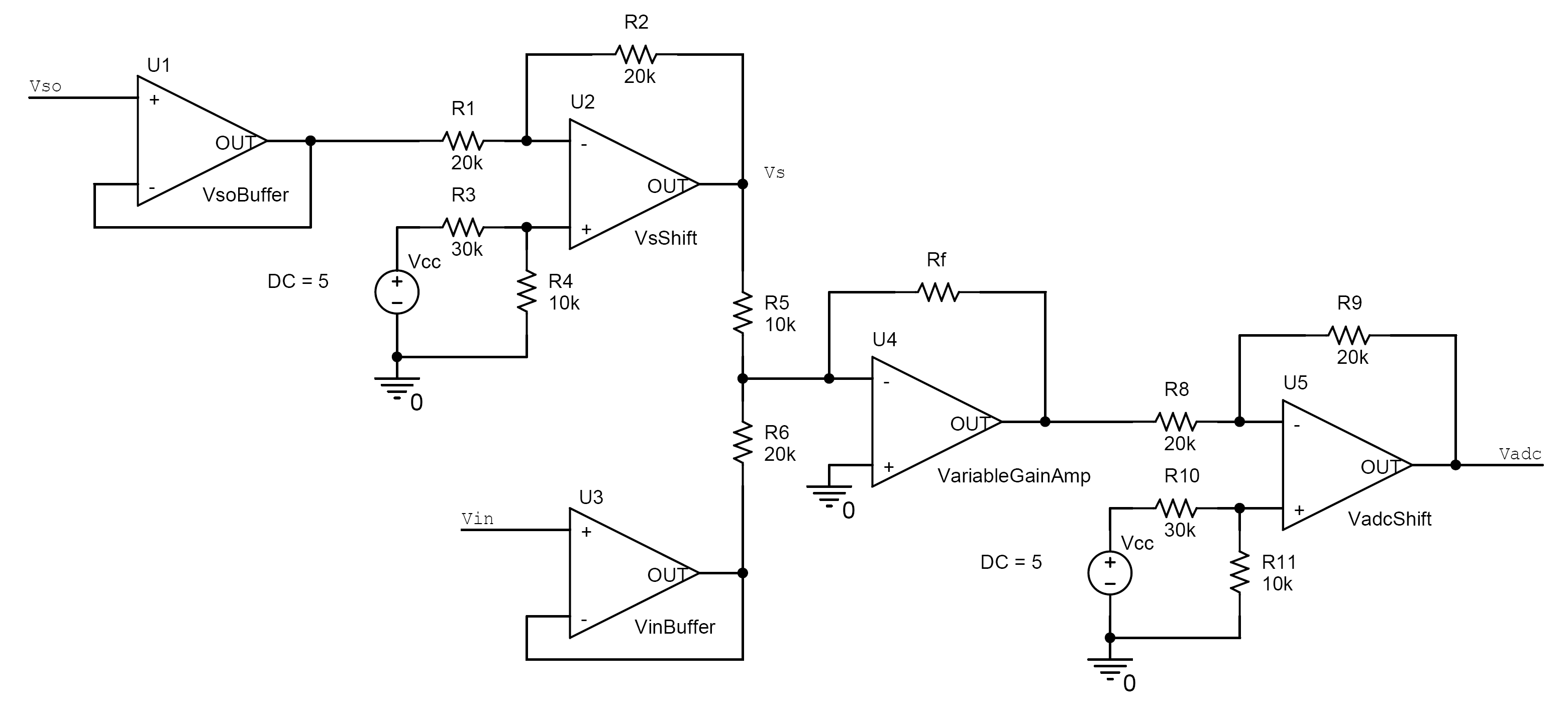
The design of the analog circuit preceding the ADC is critical for ensuring signal integrity. This circuit typically includes operational amplifiers (op-amps) configured for both amplification and level shifting. Properly designed, this circuit can enhance the signal-to-noise ratio and prevent distortion that may arise from saturation effects in the amplification process. The selection of components such as resistors, capacitors, and op-amps must be made with careful consideration of their characteristics and how they interact within the circuit.
The cutoff frequency of the analog circuit is a vital parameter, as it determines the maximum frequency at which the circuit can operate effectively. A cutoff frequency significantly higher than the Nyquist frequency of the ADC is essential to ensure that the analog signals are accurately represented in the digital domain. This design consideration minimizes the risk of aliasing and ensures that the ADC can effectively sample the incoming signals without introducing errors.
In conclusion, the interplay between digital and analog signals, the role of the ADC, and the importance of circuit design are fundamental to the successful implementation of a digital oscilloscope. The careful selection of components and adherence to design principles are paramount for achieving reliable and accurate measurements in electronic applications.For the purpose of this project, digital signals can be communicated with computers while analog signals can`t. RS232 is the name given to your serial port. At the back of your computer, there`s many ports where you can plug things into. The RS232 port has 9 pins and looks like: At the heart of most digital oscilloscopes is a device (usually a chip of some sort) which converts analog
voltage levels to digital signals. This chip is called an analog to digital converter (ADC). If this happens very quickly and the computer keeps track of voltage over time, a plot can be drawn, hence the principal of a digtal oscilloscope. How quickly the chip is able to make these conversions is called the sampling frequency. It is given in units of ksps (kilo-samples per second) or Msps (mega-samples per second). And if you know the sampling frequency to be f, the highest frequency sine wave it can detect is f/2.
This is known as the nyquist frequency. Any higher than that and all you`ll get erroneous results and an effect known as aliasing (click here for details). For my case, I chose ADC0804 because they are readily availible at Supremetroncis. This chip is guarenteed to work at 8ksps. And hence, the nyquist frequency is 4kHz. That means, the fastest sine wave I can see with chip is 4kHz before bad things start happening. Most oscilloscopes have some analog circuit which will amplify and shift the trace before it is sampled by the ADC.
By shifting the signal before amplifying it gives better accuracy in many cases (avoid saturation with amplifiers). As with all analog circuits, they will work only within a range of frequencies. After a specific frequency, the cut off frequency, the output voltage level is less than 70. 7% of the original voltage level and is considered unsuitable for measurement. It would be preferrable for this frequency to be much higher than the nyquist frequency of the ADC. While I had some knowledge of electronics hardware, I still do not understand all components fully. It is very different to sketch an opamp circuit on paper than it is to choose the correct components and lay it out to minimize noise.
So, there`s bound to be oversights where a resistor value was too low or the components were not well chosen, etc. Hence the difference between physics where it supposed to work and engineering were good approximations and correct components are key.
I`m still learning s 🔗 External reference
Related Circuits
The probe described here was designed to be used over the range of several tens of Hz to a couple MHz with currents from a few tens of milliamps to about 10 amps peak-to-peak. Formulae are given which will...
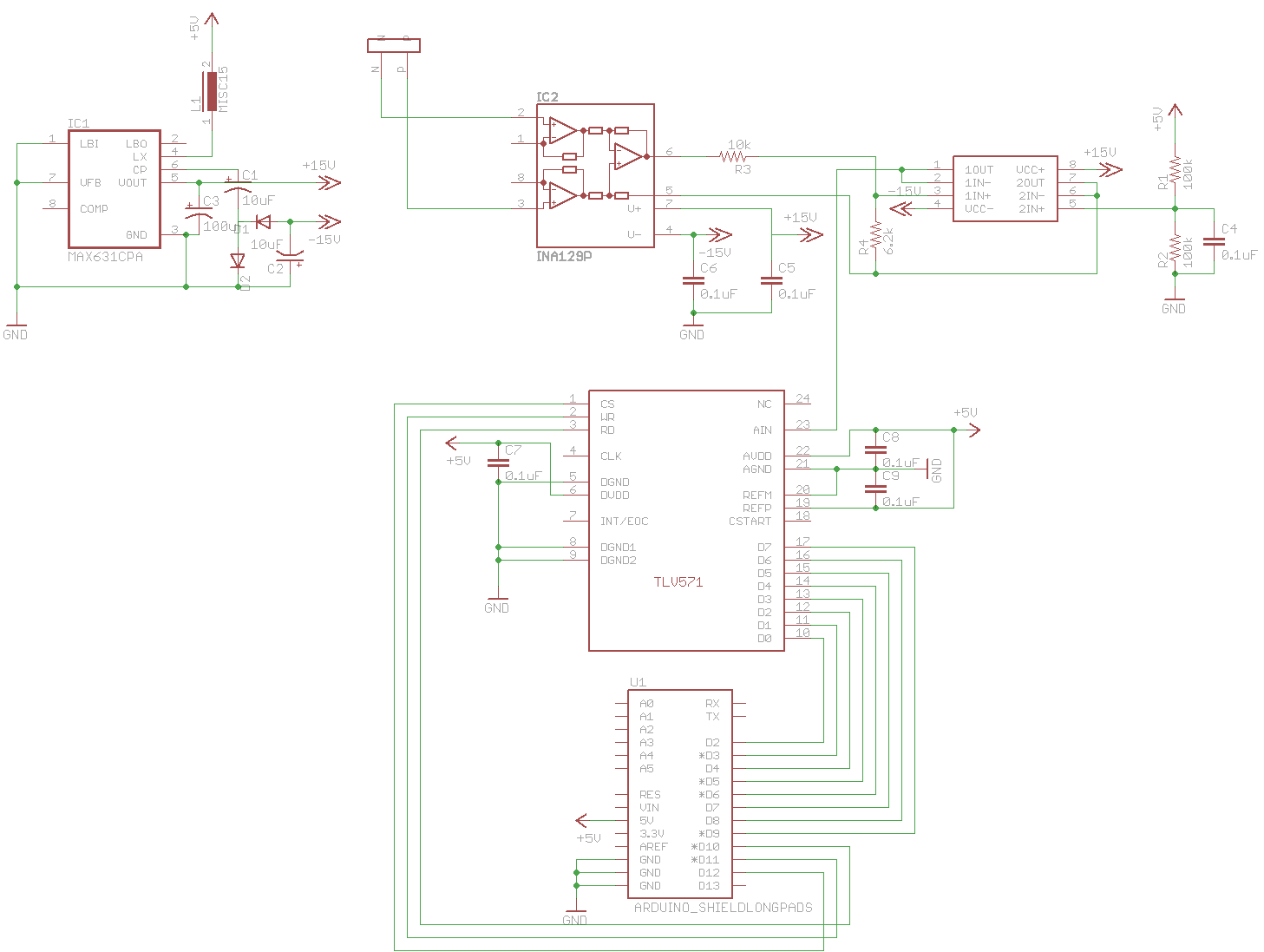
A digital oscilloscope is being developed using Arduino, designed as an Arduino Shield. The current implementation functions but exhibits signal distortions. A TLV571 chip is utilized in the design. The project involves creating a digital oscilloscope that can be mounted...
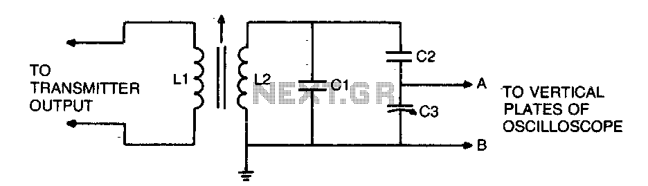
To display an RF signal, connect LI to the transmitter and points A and B to the vertical plates of the oscilloscope. Adjust LI for minimum SWR and C3 for the desired trace height on the CRT. More: L2...
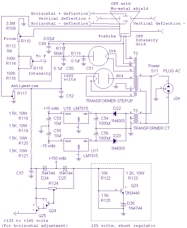
The high voltage section of the CRT is unchanged from the original vacuum tube oscilloscope used as the basis of this design. The CRT requires shielding from the main power transformer. Cold roll steel around the CRT does not...
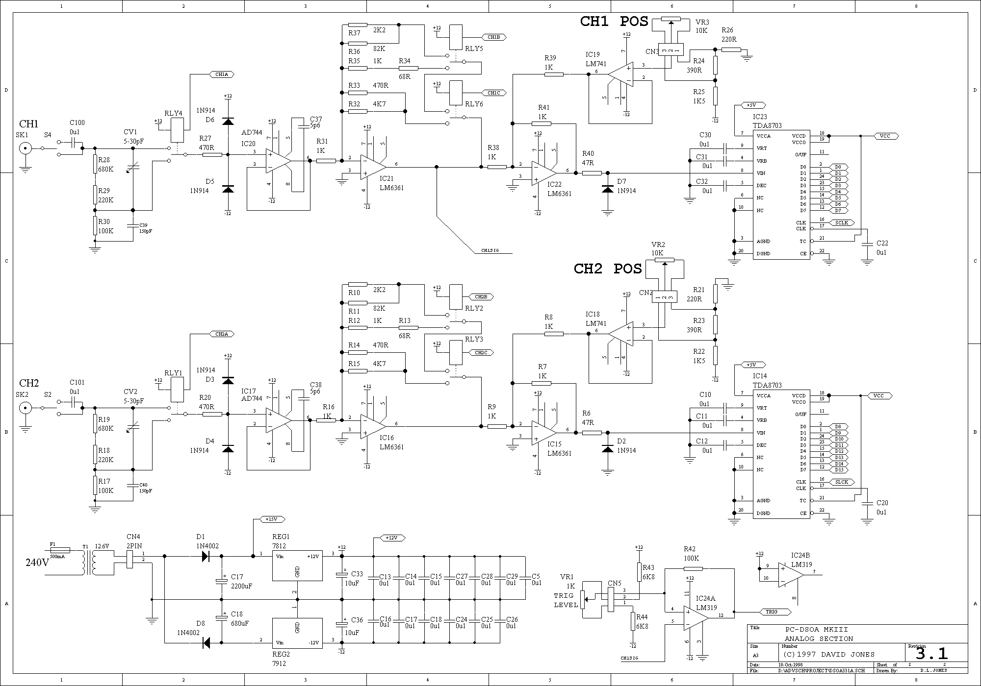
A follow up Mk2 version described by EA's Jim Rowe in the May/June/July 94 issues of EA improved on the original with calibrated time and vertical scales, and extra triggering features. This design proved even more popular than the...
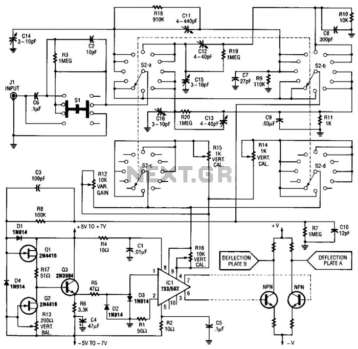
An oscilloscope front-end amplifier can be constructed using low-cost transistors and video amplifier integrated circuits (ICs). This preamplifier utilizes a FET input along with compensated attenuators, achieving an approximate bandwidth of 100 MHz, which is sufficient for most general-purpose...
Warning: include(partials/cookie-banner.php): Failed to open stream: Permission denied in /var/www/html/nextgr/view-circuit.php on line 713
Warning: include(): Failed opening 'partials/cookie-banner.php' for inclusion (include_path='.:/usr/share/php') in /var/www/html/nextgr/view-circuit.php on line 713