
Transmitter-oscilloscope coupler for CB signals
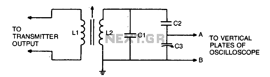
The circuit described is an RF signal display setup that utilizes an oscilloscope to visualize the signal characteristics. The primary component for signal pickup is LI, which is connected to the transmitter. This inductor is critical for ensuring a proper match between the transmitter and the load, which is achieved by adjusting LI to obtain the minimum Standing Wave Ratio (SWR). A lower SWR indicates better efficiency in power transmission and lesser reflections.
The oscilloscope's vertical plates, connected to points A and B, allow for the visualization of the RF signal. The adjustments made to C3, a 75 pF trimmer capacitor, facilitate the fine-tuning of the trace height on the cathode-ray tube (CRT), ensuring that the signal is displayed clearly and within the desired range on the screen.
The circuit also includes L2, which is constructed with 4 turns of #18 wire wound on a %" slug-tuned RF coil form. This component serves as a resonator, helping to filter and select the desired frequency range of the RF signal. The use of a slug-tuned coil allows for easy adjustments to the inductance, enabling precise tuning to the operating frequency.
Additionally, LI consists of 3 turns of #22 wire, positioned adjacent to the grounded end of LI. This configuration is essential for establishing the correct coupling between the inductor and the RF signal source, optimizing the signal transfer to the oscilloscope. The capacitors C1 and C2, each rated at 5 pF, are likely used for impedance matching or filtering purposes within the circuit, ensuring that the signal integrity is maintained throughout the system.
Overall, this schematic provides a comprehensive approach to displaying RF signals, emphasizing the importance of component selection and configuration in achieving optimal performance in RF applications.To display an rf signal, connect LI to the transmitter and points A and B to the vertical plates of the oscilloscope. Adjust LI for minimum SWR and C3 for the desired trace height on the CRT L2 = 4 turns #18 on %" slug tuned rf coil form, Ll = 3 turns #22 adjacent to grounded end of Ll, Cl, and C2 = 5 pF, C3 = 75 pF trimmer. 🔗 External reference
Related Circuits

The LT4430 drives the opto-coupler that crosses the galvanic barrier in an isolated power supply. The IC contains a precision-trimmed reference, a high bandwidth error amplifier, an inverting gain of 6 stage to drive the opto-coupler, and unique overshoot...
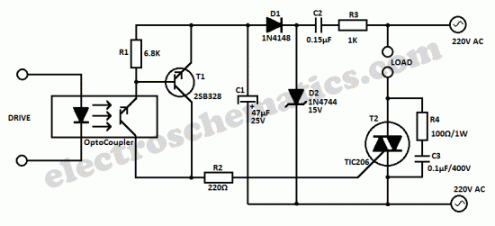
This universal triac controller circuit with optocoupler addresses the issue that triacs face when operating at low temperatures, as they require a higher gate trigger voltage. The universal triac controller circuit is designed to enhance the performance of triacs, particularly...
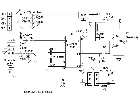
The purpose of the terminal interface is to allow my computer to communicate with Minimum Mass Wireless Coupler equipped devices using a terminal emulator program. Consequently, the Base Unit is basically an RS-232 interface and Minimum Mass Wireless Coupler....

A preamplifier in the audio frequency range amplifies a noisy audio signal to drive a diode clipper. Suitable audio input levels would be in the 10-mV to 1-V range. The audio preamplifier circuit is designed to enhance weak audio signals, typically...
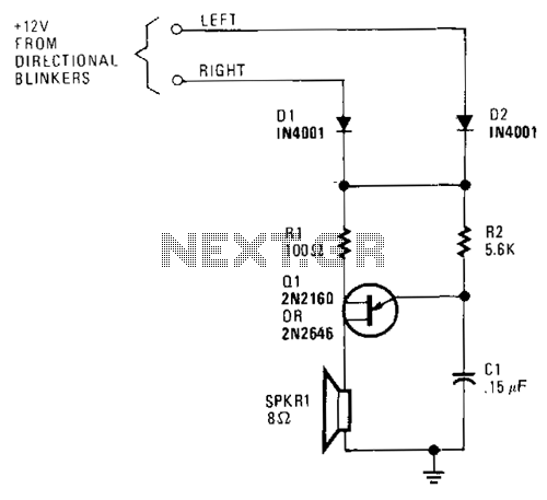
A unijunction transistor audio oscillator drives a small speaker. The oscillator's frequency is determined by resistor R2 and capacitor C2. The operating voltage is supplied from the car's turn-signal circuit(s) through D1 and D2. The diodes conduct current from...

An interface circuit utilizing optocouplers provides galvanic isolation and common-mode noise rejection between low-voltage microcontroller units and high-voltage integrated power modules in motor-drive applications. Optocouplers ensure high-voltage isolation between a low-voltage device, such as a microcontroller or a pulse-width...