
arduino based digital oscilloscope

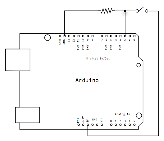
The project involves creating a digital oscilloscope that can be mounted on an Arduino platform, effectively transforming it into a shield. The TLV571 chip is a key component in this design, serving as a high-speed comparator that aids in signal processing. This chip is capable of handling analog input signals, converting them into digital signals suitable for processing by the Arduino microcontroller.
To enhance the performance of the digital oscilloscope, several factors need to be considered. First, the input signal conditioning must be optimized. This may involve using operational amplifiers to amplify weak signals and filter out noise before they reach the TLV571. Proper filtering can help reduce distortions and improve the clarity of the displayed waveform.
Additionally, the sampling rate of the Arduino must be sufficient to capture the desired frequency range of the input signals. This can be achieved by adjusting the code to ensure that the Arduino is sampling at a high enough rate to accurately represent the input waveform. Utilizing techniques such as oversampling and averaging can also help mitigate distortions and improve signal fidelity.
The output display of the oscilloscope can be implemented using an LCD or OLED screen, which can show the waveform in real-time. The user interface should allow for adjustments in time base and voltage scale, enabling users to analyze different aspects of the signal effectively.
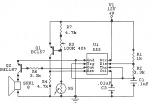
In summary, while the current digital oscilloscope design using Arduino and the TLV571 chip demonstrates basic functionality, improvements in signal conditioning, sampling rate, and display output are essential to enhance performance and reduce distortions in the received signals.I have always wanted to have an oscilloscope at home. I am trying to make a digital oscilloscope using the Arduino. I made the digital oscilloscope into an Arduino Shield. Right now, it is not very good. It works, but there are distortions in the received signal. I used a TLV571 chip which is a.. 🔗 External reference
Related Circuits
The MM5314 is a monolithic MOS integrated circuit that incorporates P-channel low threshold enhancement mode and ion implanted depletion mode devices. It features an internal multiplex oscillator, fast and slow set controls, a single power supply, 7-segment outputs, leading...

The schematic below illustrates four methods of controlling a relay with a digital logic signal. Figure A can be used in most cases where the relay coil requires 100 mA or less and the input current is 2 milliamps...
The following circuit illustrates a Sun Up Alarm Light Alarm Circuit Diagram. This circuit is based on the 555 Integrated Circuit (IC). Features include simplicity and cost-effectiveness. The Sun Up Alarm Light Alarm Circuit employs the 555 timer IC in...
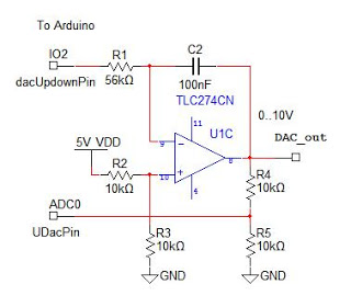
An analog output for Arduino can be achieved using a Digital-to-Analog Converter (DAC), commonly implemented with an R-2R ladder circuit. However, this DAC lacks an output buffer, which would enhance reliability and compatibility with various loads. For optimal performance,...
This circuit blanks the CRT starting just before retrace begins. Since the CRT sits at a -1200 volt potential, the blanking circuit must also be based at -1200 volts. Note the capacitors, C40, C41, and C43 which allow the...
Connect three wires to the Arduino board. The first two, red and black, connect to the two long vertical rows on the side of the breadboard to provide access to the 5-volt supply and ground. The third wire goes...