
OSU8 Microprocessor Project (1994)
The OSU8 microprocessor project is an 8-bit architecture designed to fulfill basic computational tasks. The architecture is characterized by a simplified instruction set, allowing for easy implementation and testing. The initial phase of the project involved defining the architecture, which includes the data path, control logic, and memory management. The design was subsequently implemented using a Xilinx FPGA, which provided a flexible platform for hardware testing and validation.
The use of FPGA technology allowed for rapid prototyping and iterative testing. However, despite successful gate-level simulations, the Xilinx hardware encountered stability issues, crashing after executing a limited number of instructions. This indicates potential issues in the design, such as timing violations, inadequate signal integrity, or resource contention within the FPGA.
In addition to the FPGA implementation, there was an intention to develop a full-custom CMOS version of the OSU8 microprocessor. This would involve creating a dedicated silicon chip optimized for the specific architecture, potentially enhancing performance and reliability compared to the FPGA version. The transition from FPGA to CMOS fabrication would require a thorough understanding of VLSI design principles and access to semiconductor fabrication facilities.
Further development of the OSU8 microprocessor could focus on debugging the existing hardware to identify the root cause of the crashes and improving the design for CMOS implementation. This could include refining the instruction set, optimizing the data path, and enhancing the control logic to ensure reliable operation under various conditions.OSU8 began as a student project in 1994 to create a simple but functional 8-bit microprocessor, starting with a definition of the architecture to implementation in a Xilinx FPGA chip, and full-custom CMOS implementation. Over a period of about six months, the project came together and was, more or less, a success. The Xilinx-based hardware actually ran some code, but would crash after several dozen instructions. Gate-level simulation would run code correctly. Perhaps someday I`ll revisit the project and troubleshoot the real hardware, and maybe even fab the full-custom CMOS chip.
🔗 External reference
Related Circuits
This circuit includes automatic exit and entry delays along with a timed bell cut-off feature. It accommodates both normally-closed and normally-open contacts, and it has a 24-hour personal attack/tamper zone. The circuit is permanently connected to a 12-volt supply...
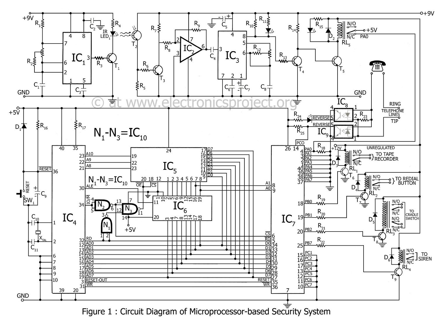
A microprocessor-based home security system project. This advanced security system not only notifies the user but also alerts the police immediately. In the 8085 microprocessor-based home security system, control is exercised over a siren, telephone (via cradle and redial...

The TDA1020 is a monolithic integrated 12 W audio amplifier housed in a 9-lead single in-line (SIL) plastic package. Although it is designed primarily for car audio applications, it can also be utilized in various other audio applications. The TDA1020...

The LTC3113 fixed frequency buck-boost DC-DC converter can be utilized to design various power supply circuits that operate with input voltages that are above, below, or equal to the output voltage. The topology integrated into the IC ensures low...
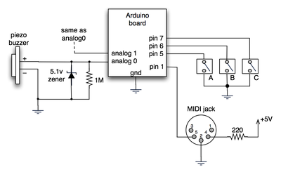
The notes for the fourth and final class are available on the Spooky Arduino class page. At the conclusion of the class, Mark from Machine Project awarded each student a merit badge. A project utilizing techniques from this week's...
The LM56 Thermostat project circuit diagram involves determining the values of resistors R1, R2, and R3 for the temperature points VT1 and VT2 using specific equations. This electronic circuit featuring the IC LM56 serves as a simple reference project....