
A circuit diagram of an amplifier circuit to enhance the output current and voltage
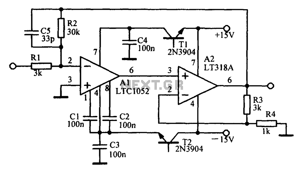
An amplifying circuit is designed to increase the amplitude of an input signal, resulting in a higher output current and voltage. This type of circuit is commonly utilized in various electronic applications, such as audio systems, instrumentation, and communication devices.
The basic components of an amplifying circuit typically include transistors (BJT or FET), resistors, capacitors, and sometimes operational amplifiers (op-amps). The configuration of these components can vary based on the desired amplification characteristics, such as gain, bandwidth, and input/output impedance.
In a common transistor amplifier configuration, the transistor operates in its active region, where it can effectively amplify the input signal. The input signal is applied to the base (or gate) of the transistor, while the output is taken from the collector (or drain). Resistors are used to set the biasing conditions of the transistor, ensuring it remains in the active region during operation. Coupling capacitors may be employed to block DC components while allowing AC signals to pass through, thereby isolating different stages of amplification.
For further enhancement of performance, feedback mechanisms can be introduced. Negative feedback can stabilize the gain and improve linearity, while positive feedback can be used in specific applications to increase gain further. The choice of components and configuration will ultimately depend on the specific requirements of the application, including the desired frequency response and power handling capabilities.
In summary, an amplifying circuit is crucial for boosting signal strength in various electronic applications, and careful design considerations are necessary to achieve optimal performance.Amplifying circuit diagram to enhance the output current and voltage:
Related Circuits
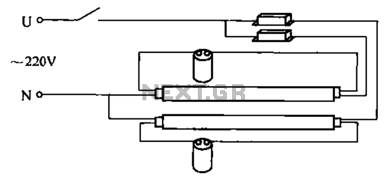
A double tube fluorescent lighting circuit is illustrated. In certain situations, a single tube light may not fulfill the lighting requirements, necessitating the use of double tube lighting. The physical installation is depicted in the circuit of a double...
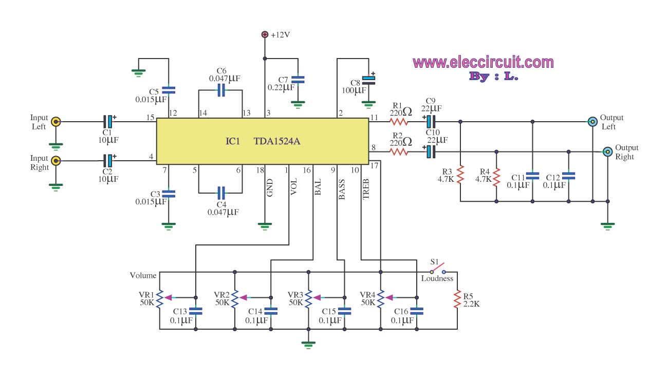
The stereo tone control circuit utilizes the integrated circuit TDA1524A. This IC serves as the central component in the design. The TDA1524A is a versatile integrated circuit designed for audio applications, particularly in tone control systems. It features a dual-channel...
Amplifier with IC number TDA7293 for processing sound systems. This amplifier includes inputs for a radio, TV, stereo, or other line-level devices. It also features a phono input for a record player, guitar, microphone, or other unamplified sources. With...
Low distortion bass and treble control for an amplifier. Circuit diagram. Electronics project. The low distortion bass and treble control circuit is designed to enhance the audio quality of an amplifier by allowing precise adjustments to the low and high-frequency...
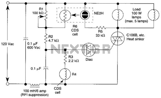
A neon bulb and a CdS photocell are enclosed in a light-tight enclosure to form an optocoupler. A diac/triac combination is employed to create a snap-switch effect. A second CdS photocell serves as the primary sensor. As darkness approaches,...
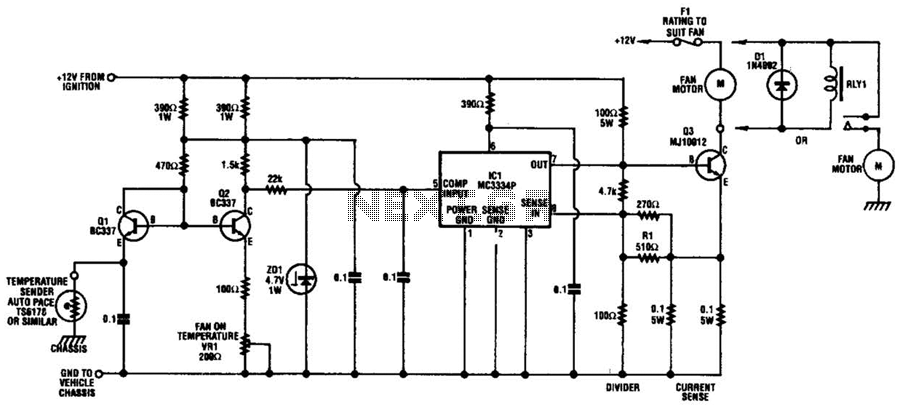
The circuit is based on a commercial temperature sensor (TS6178) and an MC3334P ignition chip. When the radiator temperature increases, the sensor pulls the base of Q2 low via Q1, which is wired as a diode. Q2's collector thus...