
Waa-waa circuit
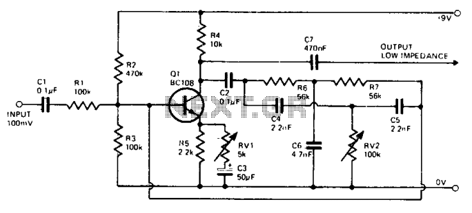
The wah-wah effect circuit primarily utilizes a phase shift RC oscillator configuration to achieve its characteristic sound modulation. This oscillator is designed to amplify specific frequency ranges, resulting in the desired tonal shift. The circuit typically consists of several resistors and capacitors arranged to create a phase shift, which is essential for oscillation.
In the circuit, RV1 functions as a variable resistor that adjusts the amplitude of the feedback signal. Initially, setting RV1 to its minimum ensures that the circuit is stable and does not oscillate. RV2, another variable resistor, is crucial for tuning the frequency of oscillation. By adjusting RV2, the user can find the precise point where the circuit begins to oscillate, indicated by the production of an audible whistle. This point is critical, as it marks the transition from a stable state to an oscillating state.
Once oscillation is achieved, further fine-tuning of RV1 is necessary. The user should gradually increase RV1 until the oscillation is just about to stop, allowing for a controlled modulation of the effect. The interaction between RV1 and RV2 allows for a wide range of frequency responses, enabling the user to explore different tonal qualities.
An important characteristic of this circuit is its ability to remain stable at various settings of RV2 without producing oscillation. This feature ensures versatility in sound design, allowing the user to experiment with different configurations while maintaining control over the effect's intensity. The wah-wah effect circuit exemplifies the principles of feedback and resonance in electronic design, making it a popular choice in audio processing applications.The waa-waa effect is achieved as certain frequencies are amplified more than others. A phase shift RC oscillator makes up the basic circuit. Negative feedback is obtained by feeding part of the signal back to the base. When adjusting initially, RV1 is turned to minimum. RV2 is adjusted to a point at which an audible whistle appears indicating oscillation. RV1 is then adjusted till the oscillation just disappears. It should be possible to set RV2 to any value without any oscillation, this should also be achieved with the minimum possible value of RV1. 🔗 External reference
Related Circuits
A device that conducts electric current and converts electrical energy into another form. Power consumed by a device or circuit while performing its function can be represented by a resistor and capacitor. The capacitor in the load circuit represents...

This liquid detector circuit diagram is designed using common electronic components. The liquid detector can activate an active buzzer to produce sound when a certain water level is reached. Since the water sensor and control circuit for the buzzer...
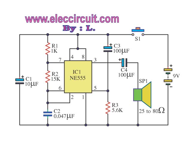
The Door Buzzer circuit utilizes an IC 555 to generate a sound resembling an electric bell. When the switch S1 is pressed, a loud sound is produced. This circuit is designed to be simple and requires minimal components. It...
This is a 25-watt basic power amplifier designed for ease of construction at a reasonable cost. It offers superior performance compared to standard STK module amplifiers commonly found in most mass-market stereo receivers produced today. The 25-watt basic power amplifier...
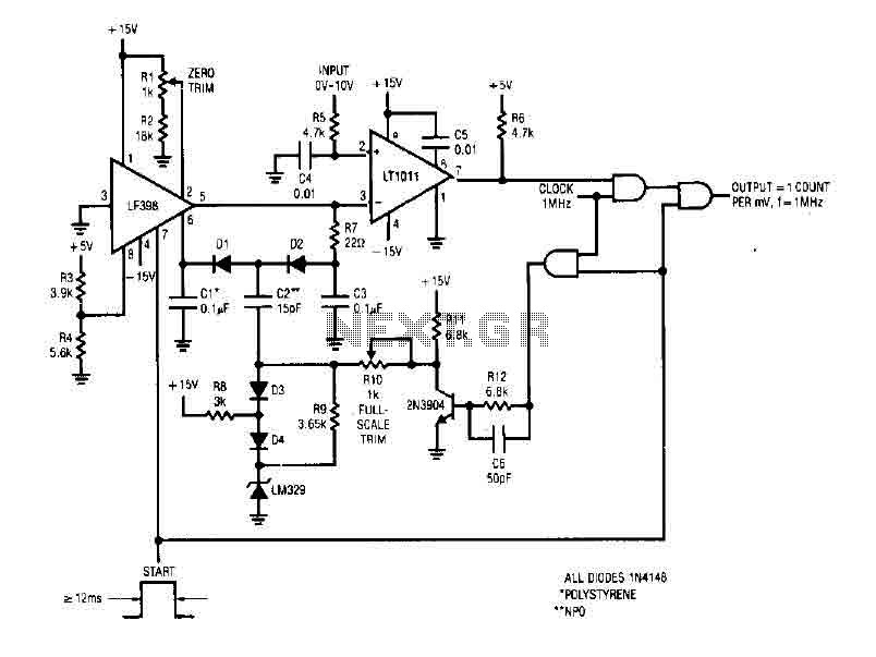
The simple 4-digit converter circuit has an output count of 1, designed for a frequency range from f-IMHz to 10.000 MHz. All diodes used in the circuit are IN4146 "POLYSTYRENE" NPO. The circuit utilizes the LF398 at the input...
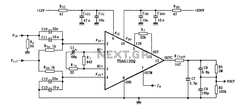
Feedback has indicated that the TDA6120Q test circuit, as shown in the figure, utilizes an input signal (Vi) composed of resistors Ra and capacitors C10 and C11, which are fed into the TDA6120Q at pins 2, 3, and 4....
Warning: include(partials/cookie-banner.php): Failed to open stream: Permission denied in /var/www/html/nextgr/view-circuit.php on line 713
Warning: include(): Failed opening 'partials/cookie-banner.php' for inclusion (include_path='.:/usr/share/php') in /var/www/html/nextgr/view-circuit.php on line 713