
P89v51rd2 Interface With Adc Mcp3202
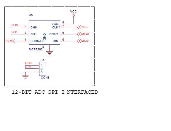
In this design, the MCP3202 analog-to-digital converter (ADC) is utilized to convert analog signals into digital data that can be processed by the P89V51RD2 microcontroller. This ADC features a 12-bit resolution and employs the Serial Peripheral Interface (SPI) protocol for communication. The connection layout is essential for ensuring proper data transfer between the ADC and the microcontroller.
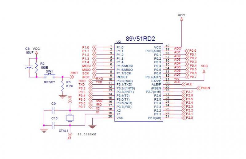
The microcontroller's pins are designated as follows:
- Chip Select (CS) is assigned to P2.2, which enables the ADC when pulled low.
- Master Out Slave In (MOSI) is connected to P1.5, allowing data to be sent from the microcontroller to the ADC.
- Master In Slave Out (MISO) is connected to P1.6, facilitating data transfer from the ADC to the microcontroller.
- Serial Clock (SCK) is connected to P1.7, which synchronizes the data transmission.
The LCD is used for displaying the ADC readings and is connected to the microcontroller as follows:
- Data lines are connected to P0.
- Register Select (R/S) is connected to P3.6, which determines whether the data being sent is command or data.
- Enable (E/N) is connected to P3.7, which is used to latch the data presented on the data lines.
The software implementation involves initializing the LCD and configuring the SPI settings. The code includes functions for sending commands to the LCD, initializing the display, and reading data from the MCP3202. The ADC readings are processed and displayed on the LCD in real-time. The program follows a loop where it continuously reads the ADC output, formats the data, and displays it on the LCD, providing a visual representation of the analog input signal.
The SPI communication is initiated by setting the CS pin low, followed by sending a command to the ADC to read the data. The received data is then processed to extract the relevant information, which is displayed on the LCD. Proper timing and delays are implemented to ensure accurate communication between components.
This setup not only illustrates the interfacing of an ADC with a microcontroller but also demonstrates the integration of a display component for user feedback, making it suitable for a variety of applications requiring analog signal processing.In this interface session we are interface mcp3202 adc interface with 8051 microcontroller. Mcp3202 is a 12bit spi protocol adc, is interface with P89v51rd2 microcontroller,this microcontroller have spi protocol so no need to worry about SDI,SDO,CLCK. Interface mcp3202 to 8051 microcontroller CS is P2.2 and MOSI is connected to P1.5 and MISO is P1.6, SCK is P1.7 refer the P89v51rd2 datasheet and MCP3202 datasheet.In this session our kit LCD P0 is for Data and P3.6 is R/s Register Select and P3.7 is for E/N Enable pin.You have interface these adc is very easy just copy we code and compile using keil or Ride compiler without no errors.
U have to only P89v51rd2 compiler because the spi protocol library function is there in the header file.
In this session our kit LCD P0 is for Data and P3. 6 is R/s Register Select and P3. 7 is for E/N Enable pin. You have interface these adc is very easy just copy we code and compile using keil or Ride compiler without no errors. U have to only P89v51rd2 compiler because the spi protocol library function is there in the header file.
#include "p89v51rd2. h" #include "stdio. h" #include "string. h" #define LCD_clear() LCD_command(0x01) /* Clear display LCD */ #define LCD_origin() LCD_command(0x02) /* Set to origin LCD */ #define LCD_row1() LCD_command(0x80) /* Begin at Line 1 */ #define LCD_row2() LCD_command(0xC0) sbit rs = P36; sbit en = P37; sbit cs = P22; void delay (); void display(int name1); void spi (); // <7465> *// void lcd_en () { // rw=0; en = 1; en = 1; en = 1; en = 0; en = 0; } void LCD_delay(unsigned char ms) { unsigned int n; unsigned int i; for (n=0; n { for (i=0; i<1535; i+); /* For 1 ms */ } } void LCD_command(unsigned char command) { rs=0; rs = 0; P0 = command; lcd_en (); LCD_delay(1); } void LCD_init() { LCD_command(0x38); LCD_command(0x06); LCD_command(0x0c); LCD_command(0x01); } void LCD_putc(unsigned char ascii) { rs=1; P0 = ascii; lcd_en (); LCD_delay(2); } void LCD_puts(unsigned char *lcd_string) { while (*lcd_string) { LCD_putc(*lcd_string+); } } void display(int name1) //LCD display routine for digits display { rs = 1; P0 = name1; lcd_en(); LCD_delay(10); } void delay1() { int i =20000; while(i-); } // <7465> *// void spi () { SPCTL = 0X5C; } void main (void) { char c, i; int e=0; LCD_init(); spi (); cs = 0; while(1) { SPDAT = 0XC0; while (SPCFG != 0X80); SPCFG = 0; c = SPDAT; SPDAT = 0XFF; while(SPCFG != 0X80); SPCFG = 0; i = SPDAT; cs = 1; cs = 1; cs = 0; e = c; e = e<<8; e = e | i; e = e<<1; e = e & 0x0fff; LCD_puts("MCP3202 ADC");//display in LCD LCD_command(0xc0); delay1(); { display(e%10000)/1000)+48); //, display(e%1000)/100)+48); //, display(e%100)/10)+48); //, display(e%10)+48); //, } delay1(); LCD_delay(500); LCD_command(0xc5); LCD_command(0x01); printf("%d ", e); }
Related Circuits
Building circuits to interface an Amiga A1200 to a PC AT/ATX power supply and tower case. To create a reliable interface between an Amiga A1200 and a PC AT/ATX power supply and tower case, it is essential to design a...

Cable and xDSL modems are increasingly popular, leading to a need for designs that interface with existing telephones at subscriber locations. The subscriber line interface circuit (SLIC) within the modem must ring the phone and provide loop current during...
The Common Mode Rejection Ratio (CMRR) facilitates the rejection of high-frequency common-mode voltages, leading to the attenuation of elevated ambient noise levels from utility lines, industrial machinery, and other sources of radiation. The circuit diagram presented illustrates the advantages...
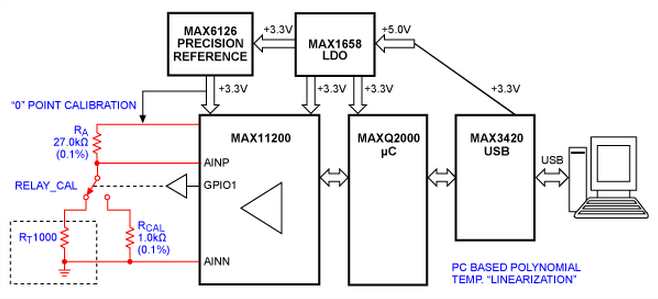
This article explains how platinum resistance temperature detectors (PRTDs) can perform measurements over wide temperature ranges of -200 °C to +850 °C, with absolute accuracy and repeatability better than ±0.3 °C, when used with modern processors capable of resolving...
Temperature indicators and temperature-based products have garnered significant interest due to their numerous applications and various possible solutions, each presenting unique advantages and disadvantages. This concept focuses on a sensor interface that delivers high accuracy while minimizing board space....
This project involves controlling an AVR microcontroller (MCU) using Visual Basic 6. The applications of this circuit are numerous, enabling the creation of various devices that require control from a Personal Computer (PC) or any circuit that collects data...