
Precision oscillator
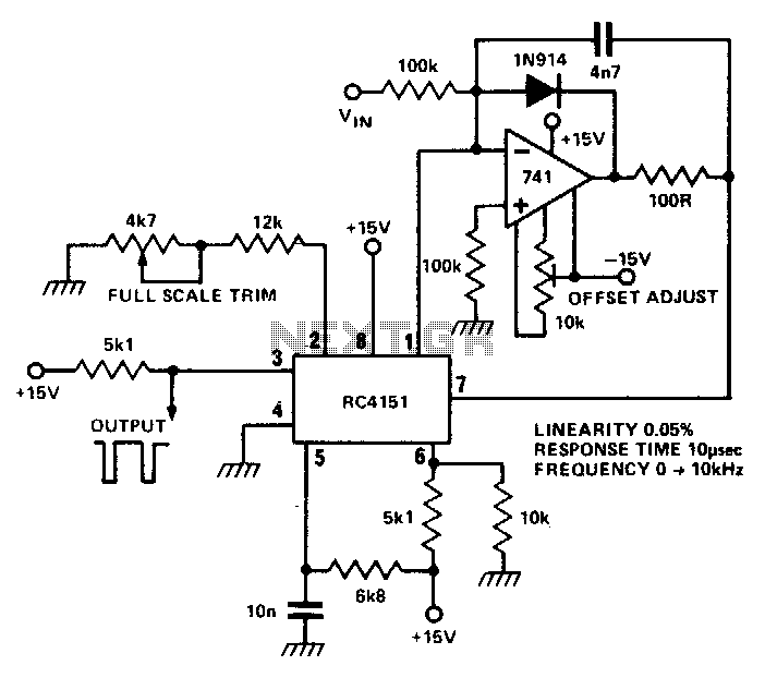
The RC 4151 is a highly accurate voltage-to-frequency converter designed for applications requiring precise frequency output based on varying voltage levels. This device operates by converting an analog input voltage into a digital pulse train, where the frequency of the output pulses is directly proportional to the amplitude of the input voltage.
The internal architecture of the RC 4151 typically includes a voltage comparator, a timing circuit, and a pulse generator. The voltage comparator compares the input voltage against a reference voltage to determine the output frequency. As the input voltage increases, the frequency of the output pulse train also increases linearly, making it suitable for applications such as analog-to-digital conversion, signal processing, and frequency modulation.
The RC 4151 can be used in various applications including data acquisition systems, frequency modulation transmitters, and precision measurement instruments. Its ability to provide a stable and repeatable output makes it an ideal choice for engineers and designers looking for reliable voltage-to-frequency conversion. Additionally, the device may include features such as temperature compensation and low power consumption, further enhancing its applicability in sensitive electronic systems.
When designing circuits with the RC 4151, careful consideration must be given to the power supply requirements and the input voltage range to ensure optimal performance. Proper filtering and decoupling techniques should also be employed to minimize noise and ensure accurate frequency output.RC 4151 precision voltage-to-frequency converter generates a pulse train output linearly proportional to the input voltage. 🔗 External reference
Related Circuits
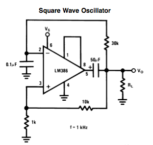
Here is a small LM386-based square-wave oscillator constructed from the following schematic. A 50k potentiometer was used in place of a 30k resistor, which functions as a pitch controller. The audio provided consists of track recordings made in Ableton...

This circuit is an oscillator utilizing astable mode operation, based on the 555 timer integrated circuit (IC). It functions as a free-running oscillator. The operation begins when the capacitor (C) charges towards 2/3 of the supply voltage (V+) through...
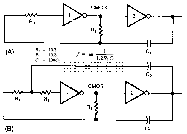
The common clock oscillator illustrated in Fig. 68-19A has two minor issues: it may not oscillate if the transition regions of its two gates differ. If it does oscillate, it might occasionally operate at a slightly lower frequency than...
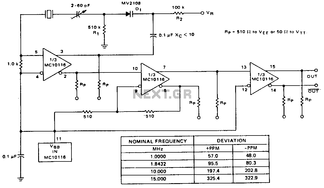
A voltage-variable capacitance tuning diode is connected in series with the crystal feedback path. Adjusting the voltage on the variable resistor (VR) changes the capacitance of the tuning diode, which in turn tunes the oscillator. The 510 kΩ resistor...
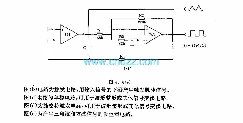
Figure a illustrates a multivibrator circuit capable of generating a square wave signal. Figure b depicts a flip-flop circuit that utilizes the falling edge of the input signal to produce a trigger pulse signal. Figure c represents a monostable...
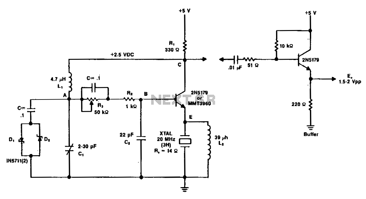
A typical circuit operating at 20 MHz is illustrated. The crystal, featuring an internal series resistance (Rs) of 14 ohms, oscillates at its third harmonic frequency. Diode clamps D1 and D2 ensure constant amplitude control. The transistor functions continuously...
Warning: include(partials/cookie-banner.php): Failed to open stream: Permission denied in /var/www/html/nextgr/view-circuit.php on line 713
Warning: include(): Failed opening 'partials/cookie-banner.php' for inclusion (include_path='.:/usr/share/php') in /var/www/html/nextgr/view-circuit.php on line 713