
Variable capacitor and Crystal radio
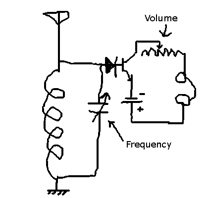
The described circuit involves an LC (inductor-capacitor) configuration that is commonly used in radio frequency applications for tuning to specific stations. The primary function of the LC circuit is to resonate at a particular frequency determined by the values of the inductor (L) and the capacitor (C). Adjusting the capacitance allows for tuning to different radio frequencies.
The necessity of a second capacitor for demodulation indicates that the circuit is likely intended for amplitude modulation (AM) or frequency modulation (FM) signals. Demodulation is the process of extracting the original information signal from the modulated carrier wave. The second capacitor could serve as a coupling capacitor or as part of a demodulation circuit, such as a simple envelope detector for AM signals.
The notion of utilizing aluminum foil as a variable capacitor suggests an interest in creating a capacitive element through the use of parallel plates. The capacitance (C) of a parallel plate capacitor is given by the formula:
C = (ε * A) / d
where ε is the permittivity of the dielectric material between the plates, A is the area of one of the plates, and d is the distance between the plates. The challenge lies in achieving the necessary precision in spacing and area to create a functional variable capacitor. The idea of having a large area of aluminum foil spaced very closely together is theoretically sound, but practically difficult due to the required tolerances.
The identified flaw in the circuit design, where two components are only connected at a single point, emphasizes the importance of establishing a complete and functional circuit path. The suggestion to connect the emitter of the transistor to the ground point of the oscillator is crucial for ensuring that the transistor operates correctly within the circuit. This connection would provide a stable reference point for the circuit and help in maintaining the proper biasing of the transistor, which is essential for its operation in amplifying the signal or switching.
In summary, this project involves the design of a tunable LC circuit for radio frequency applications, with considerations for demodulation and the innovative use of aluminum foil as a variable capacitor. The circuit must be carefully designed to ensure proper connections and functionality, particularly with the inclusion of the transistor in the design.This should let me select a station by adjusting capacitance in an LC circuit. But, the signal is still modulate it. To demodulate it, I apparently need a second capacitor there somewhere. And I have no idea how should that one part work. All I have is some aluminium foil, enough wires, and 3 normal capacitors: 1000,47, and 10 micro farads. Perhaps there is a circuit to make a normal one into adjustable I`d try to do it with aluminium, but I can`t come up with calculations. From what I see, if it`s flat plate conductor, even a whole square meter of aluminum would have to be placed at a fraction of a micrometer away from each other. That just can`t be right. 3) : yes, there is one serious error: it doesn`t make sense to have a circuit consisting of two parts that are only connected at one point.
And your circuit is just that, the single connection being the diode. I suggest connecting the emitter of your transistor to the ground point of the oscillator. 🔗 External reference
Related Circuits
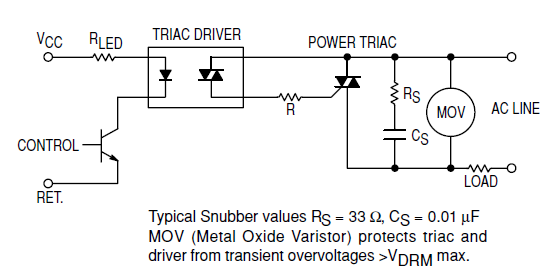
Interfacing the BT139-600 TRIAC with the MOC3051-M Opto-triac requires the construction of a snubber circuit as illustrated in the MOC3051M opto-triac's datasheet on page 8, figure 12. The load connected to this circuit will be a 230V AC, 4A...
An audible field strength indicator (AFSI) allows users to listen to variations in radio signal strength, aiding in the detection of concealed antennas. This design utilizes inexpensive and readily available components, integrating a sensitive amplified field strength detection circuit...
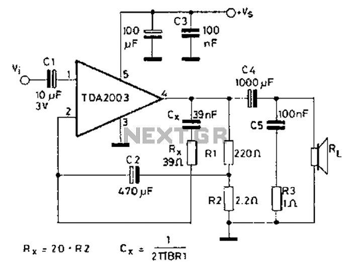
In 2003, the US Trade and Development Agency enhanced the performance of a device maintaining the same pin configuration as in 2002. The agency introduced additional functions in 2002 while ensuring a minimal number of external components, facilitating easy...
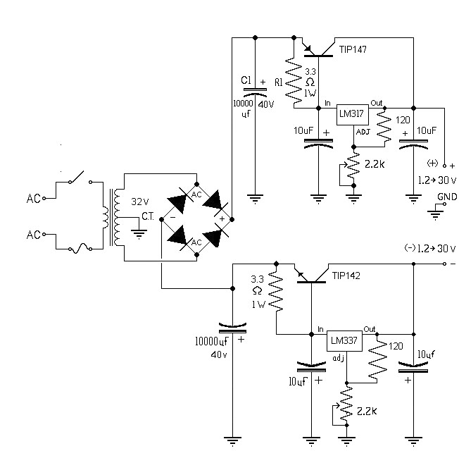
The 10A variable power supply circuit is symmetrical and can provide a symmetrical output voltage ranging from ±1.2 volts to ±30 volts DC, with a maximum current of 10A. This circuit utilizes symmetrical variable voltage regulators LM317 and LM337,...
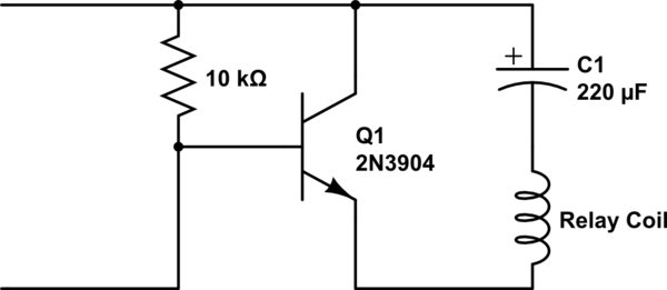
A single-coil latching relay is utilized, which can latch and reset with opposite polarities. Testing of the circuit with dual opposite-biased LEDs showed no flickering in either direction, indicating stable charge and discharge behavior. However, there are concerns regarding...
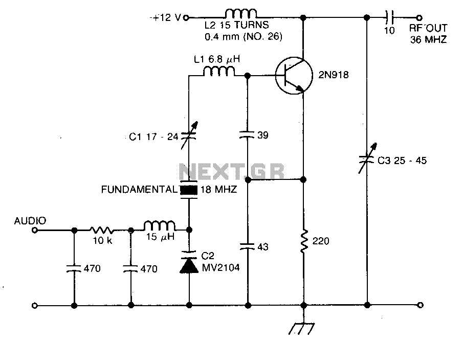
The crystal operates into a complex load at series resonance. L1, C1, and C2 balance the crystal at zero reactance. Capacitor C1 fine-tunes the center frequency. A tank circuit consisting of L2 and C3 doubles the output frequency, allowing...