
100Khz crystal calibrator

The circuit design features a 100 kHz oscillator, which serves as the primary frequency source for calibration. This oscillator typically employs a crystal to ensure stability and precision in the output frequency. The harmonics generated by the oscillator play a crucial role in the calibration process, allowing the operator to pinpoint various frequencies across the shortwave band effectively.
In the circuit, the crystal oscillator provides a stable frequency reference. The feedback voltage divider is integral to maintaining the oscillation, and the crystal's shunt configuration helps to optimize the feedback loop for consistent performance. The inclusion of the variable capacitor (C3) allows for fine-tuning of the oscillator's frequency, enabling the user to adjust the output to match specific calibration needs. This adjustability is particularly important in applications involving diverse shortwave frequencies, as it enhances the versatility of the calibrator.
For optimal performance, the output of the calibrator is coupled to the antenna circuit of the shortwave receiver. This coupling can be achieved through various means, such as a direct connection or via a matching network, depending on the specific requirements of the receiver and the desired calibration accuracy. The careful design of the circuit ensures minimal signal loss and distortion, thereby facilitating accurate frequency identification on the shortwave dial.
Overall, this calibration circuit is a valuable tool for operators seeking to enhance their shortwave listening experience by ensuring that their receivers are accurately tuned to the desired frequencies. The combination of a stable oscillator, adjustable components, and effective coupling techniques contributes to the reliability and functionality of the circuit in practical applications.This circuit is often used by amateur radio operations, shortwave listeners, and other operators of shortwave receivers to calibrate the dial pointer. The oscillator operates at a fundamental frequency of 100 kHz, and the harmonics are used to locate points on the shortwave dial, provided that the output of the calibrator is coupled to the antenna circuit of the receiver
The crystal shunts the feedback voltage divider, and is in series with a variable capacitor (C3) that is used to set the actual operating frequency of the calibrator.
Related Circuits
Here is the schematic diagram for a very basic crystal radio set without any particular embellishments. This basic old time radio uses no power other than that provided by the transmitting antenna from the radio station. Free power from...
The schematic illustrates the division of a crystal oscillator signal by the crystal frequency to achieve a precise 1-second time base with an accuracy of 0.01%. Two cascaded 12-stage counters (CD4040) create a 24-stage binary counter, with specific bits...
Adapting a failed Tesla coil into a crystal radio set for demonstration purposes has presented challenges, particularly with antenna size for optimal signal reception. It has been noted that an ideal AM antenna should range between 100 to 500...

Building a signal generator is an essential project for any analog DIY enthusiast. While already possessing a bench signal generator, the intention was to create a compact, battery-powered device for quickly testing new effect designs. An enclosure from a...
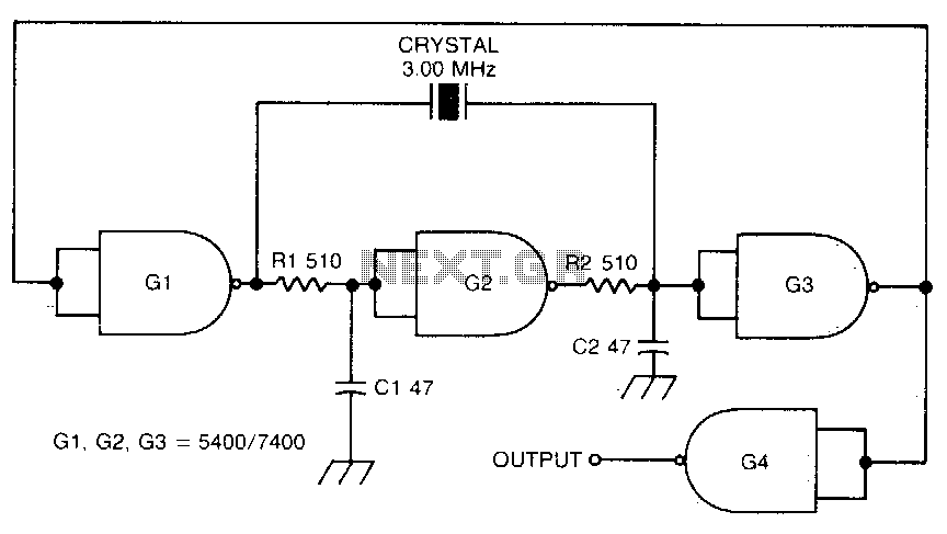
This circuit oscillates without the crystal. When the crystal is included in the circuit, the frequency will match that of the crystal. The circuit exhibits good starting characteristics even with low-quality crystals. This circuit design features a basic oscillator configuration...
There is a significant amount of vintage amateur equipment that many enthusiasts have chosen to restore and rejuvenate. Although many early amateur transceivers operate effectively, they typically lack a digital readout and depend on analog dials for tuning. The...