
Parallel Port Break Out Board
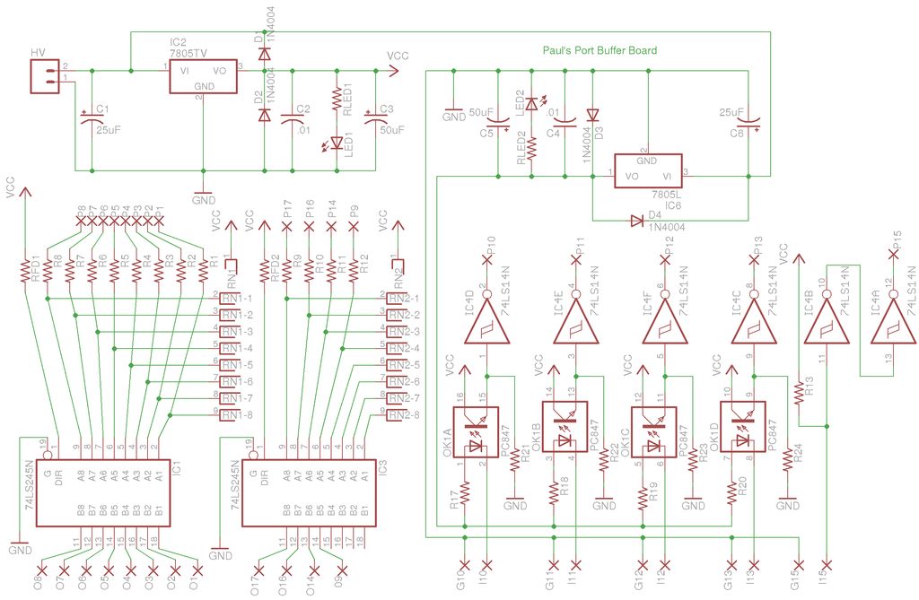
The buffer board serves as an essential component in various electronic circuits, acting to isolate different sections of a system while ensuring signal integrity. It typically consists of operational amplifiers or dedicated buffer ICs that provide high input impedance and low output impedance, which is crucial for preventing signal degradation.
The design of the buffer board may include multiple input and output channels to accommodate various signal sources and destinations. Each channel can be equipped with gain control, allowing for the adjustment of signal levels to match the requirements of subsequent circuit stages. Additionally, the board may incorporate bypass capacitors to filter out high-frequency noise, enhancing overall performance.
Power supply considerations are vital; the buffer board should be designed to operate within a specified voltage range, often utilizing a dual supply configuration to accommodate both positive and negative signal swings. Input and output connections can be made via terminal blocks or connectors, facilitating easy integration into existing systems.
To ensure reliability, the board layout should minimize trace lengths and avoid sharp angles, which can introduce unwanted inductance and capacitance. Ground planes may be implemented to reduce electromagnetic interference and provide a stable reference for the signals.
In summary, the buffer board is a versatile device that can be adapted for a variety of applications, from audio processing to data communication, ensuring that signals are transmitted accurately and efficiently across different parts of an electronic system.Let me begin by saying I built my buffer board with a specific project in mind but I`d like to present it here as more of a general application devic.. 🔗 External reference
Related Circuits
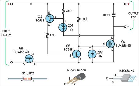
This circuit is designed to power a laptop computer using a solar power setup. The computer requires 12V at 3.3A. The circuit employs a linear regulator with a MOSFET (Q4) as the series pass device. A 100kΩ resistor provides...
This circuit is a simple air flow detector that signals the presence of air flow. The sensor utilized is a filament incandescent lamp. Components include an air flow detector, a sensor, an LED, and an LM339 operational amplifier. The air...
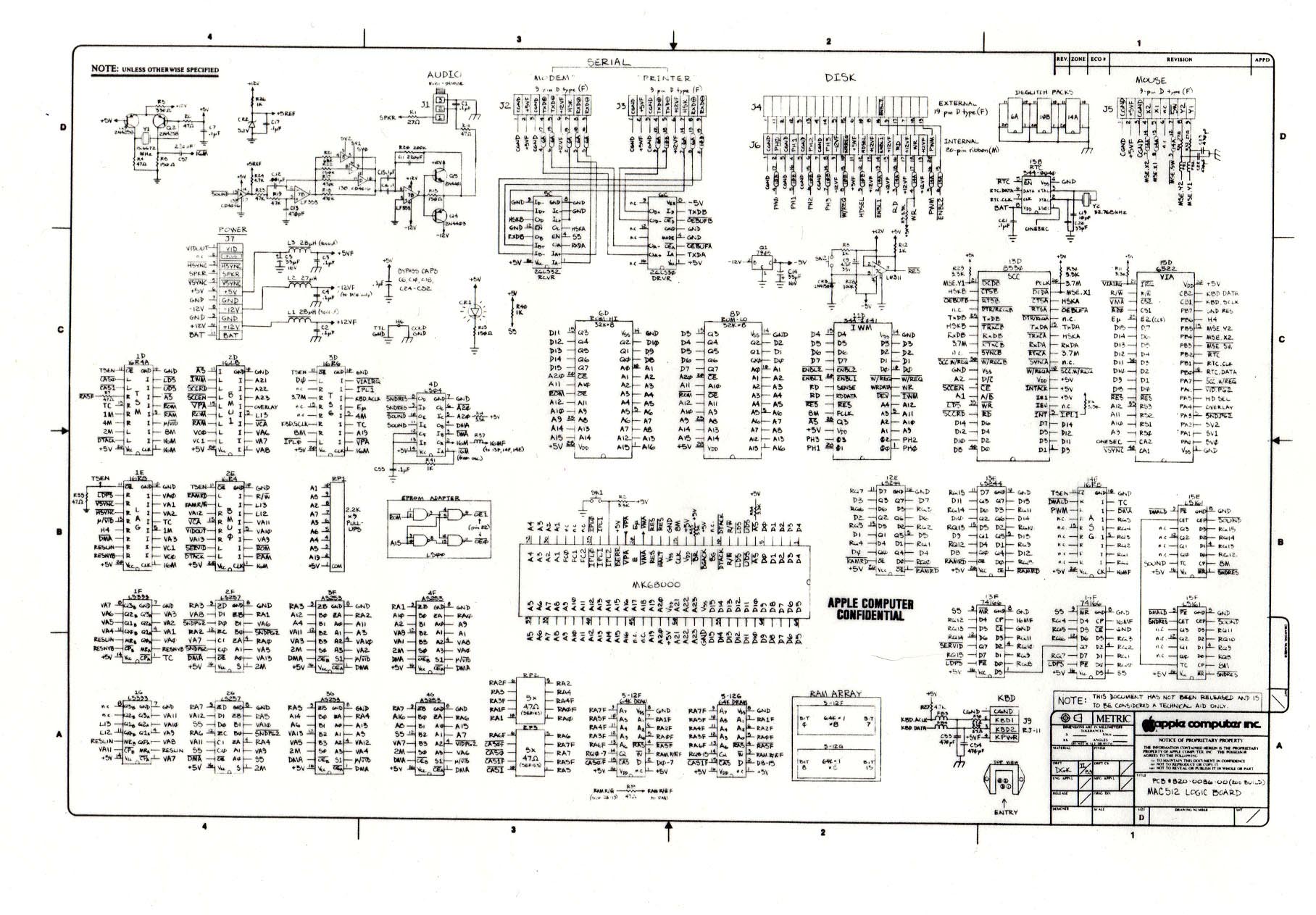
The following is one of the rare and significant documents at DigiBarn, the only known copy of the complete schematic specification for the 512K Macintosh Logic Board. Co-authored by Daniel Kottke, this design served as the foundation for the...
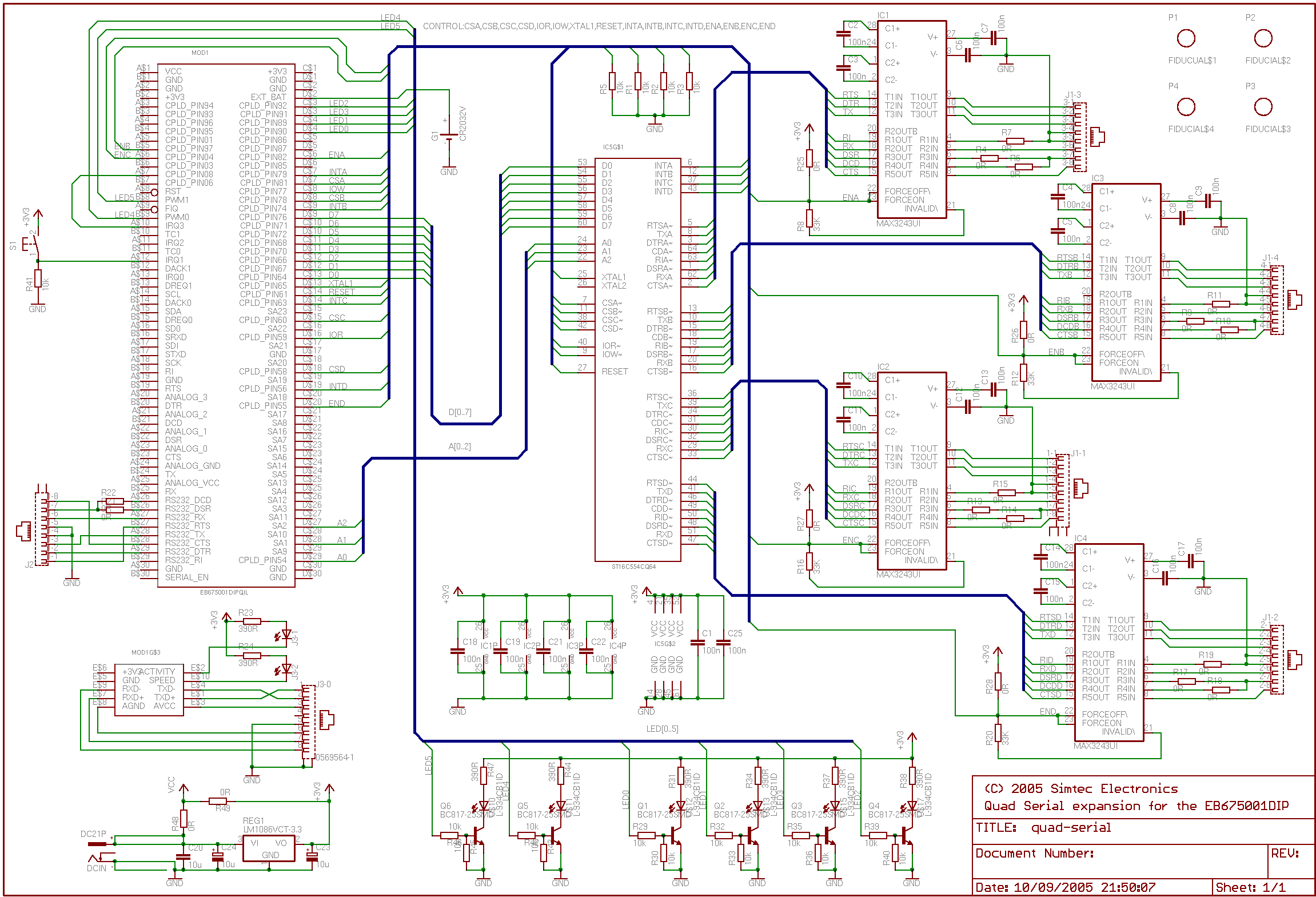
This application note outlines the creation of a basic framebuffer with PAL composite TV output for the EB675001DIP. The design employs a minimal number of additional components to facilitate this display. A user-configurable CPLD is utilized to provide all...
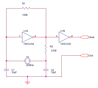
The 74HCU04 is a chip designed for specific circuit applications, while the HCT variant may not be suitable for such configurations. Capacitors C1 and C2 can be utilized up to 33pF, and resistor R2 can be adjusted to achieve...
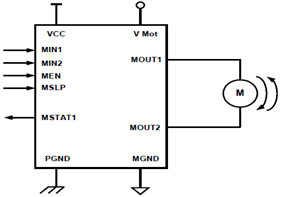
The schematic presented illustrates a 5A H-Bridge Module designed for the operation of a single Bipolar DC motor. The H-Bridge Module includes a header set (J2) and a connector terminal set (J1). Below is the pinout description for the...