
passive low pass filter remove RF
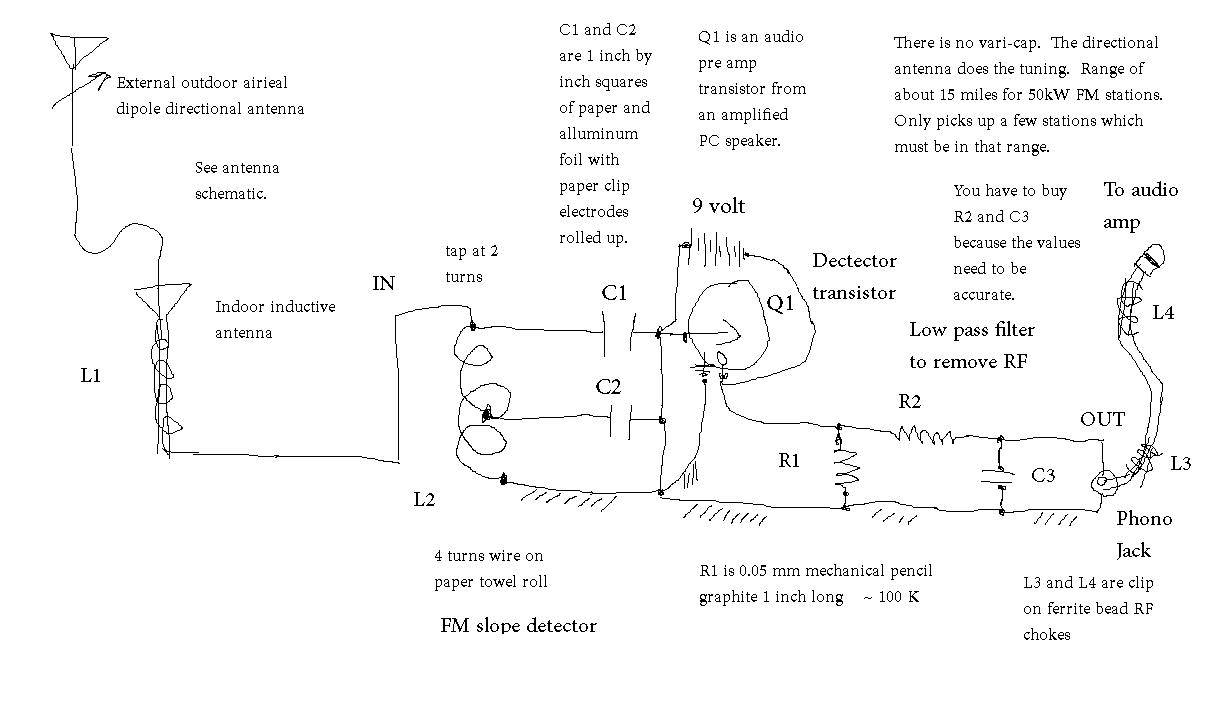
A low-pass filter is an essential component in radio frequency applications, particularly for crystal sets, where it is crucial to remove unwanted high-frequency signals that can interfere with the desired audio output. The design of a low-pass filter typically involves selecting resistor (R) and capacitor (C) values that determine the cutoff frequency (fc) of the filter.
The cutoff frequency is defined by the formula:
fc = 1 / (2πRC)
Where:
- fc is the cutoff frequency in Hertz (Hz),
- R is the resistance in ohms (Ω),
- C is the capacitance in farads (F).
To effectively remove RF interference, the cutoff frequency should be set below the frequency of the undesired RF signals while allowing the desired audio frequencies to pass through. For instance, if the target audio frequencies range from 300 Hz to 3 kHz, the cutoff frequency may be set around 3 kHz to ensure that the filter attenuates higher RF frequencies while preserving the audio signal.
To select appropriate resistor and capacitor values, one can rearrange the cutoff frequency formula. For example, if a capacitor value of 10 nF (10 x 10^-9 F) is chosen, the resistor value can be calculated as follows:
R = 1 / (2πfcC)
Assuming a cutoff frequency of 3 kHz:
R = 1 / (2π(3000)(10 x 10^-9)) ≈ 5.3 kΩ
Alternatively, if a standard resistor value of 4.7 kΩ is selected, the corresponding capacitor value can be calculated:
C = 1 / (2πRfc)
Using R = 4.7 kΩ and fc = 3 kHz:
C = 1 / (2π(4700)(3000)) ≈ 11.3 nF
The selection of resistor and capacitor values can thus be adjusted based on the specific requirements of the application, ensuring optimal performance of the low-pass filter in removing unwanted RF signals from the crystal set. It is also advisable to consider the tolerances and power ratings of the components to ensure reliability and efficiency in the circuit design.Looking for resistor value and capacitor value for low pass filter to remove RF. The application is removing undesired untuned RF from the crystal set .. 🔗 External reference
Related Circuits
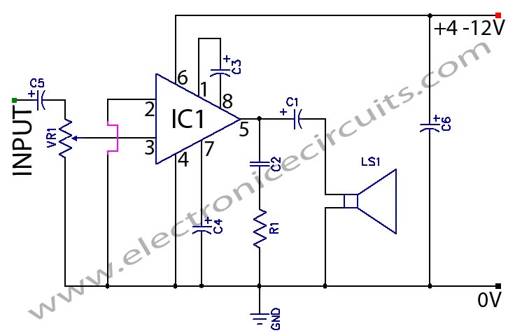
The LM386 is a power amplifier designed for use in low voltage consumer applications. The gain is internally set to 20 to minimize the need for external components. The LM386 power amplifier is a versatile component widely used in low-voltage...
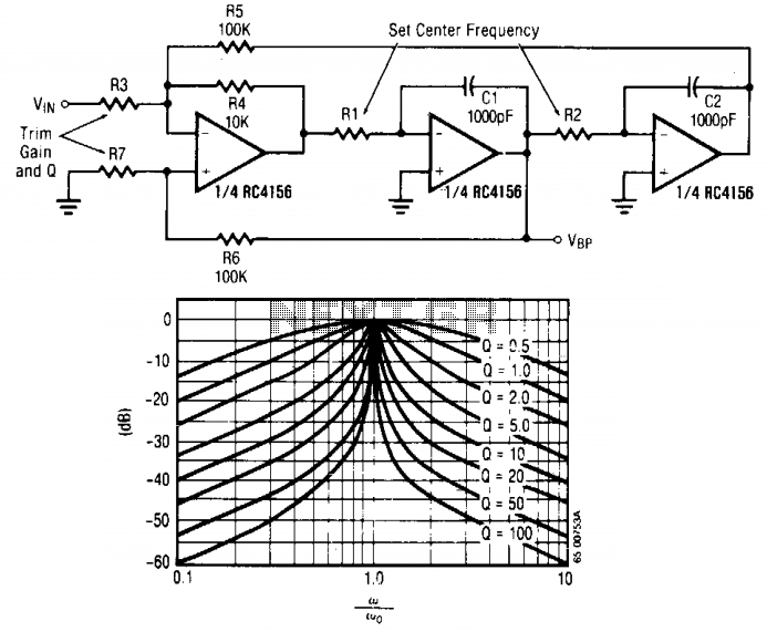
The input signal is applied through resistor R3 to the inverting input of the summing amplifier, with the output taken from the first integrator. The summing amplifier ensures that the voltage at the inverting and non-inverting inputs remains equal....
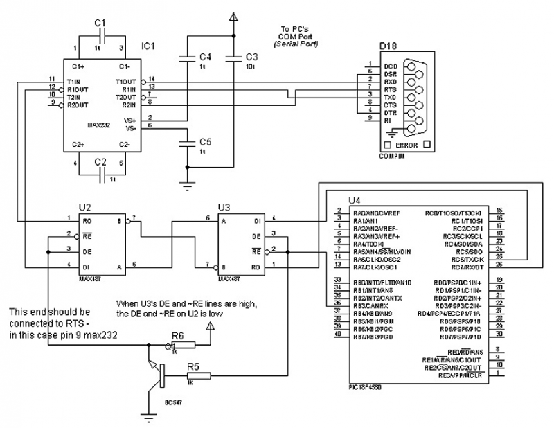
The circuit in Figure 1 is an RS-232/485 converter that uses the transmitted signal itself to control the flow. The circuit uses MAX232 and MAX483 interface circuits, IC1 and IC2 from Maxim Integrated Products to convert between the ICs'...
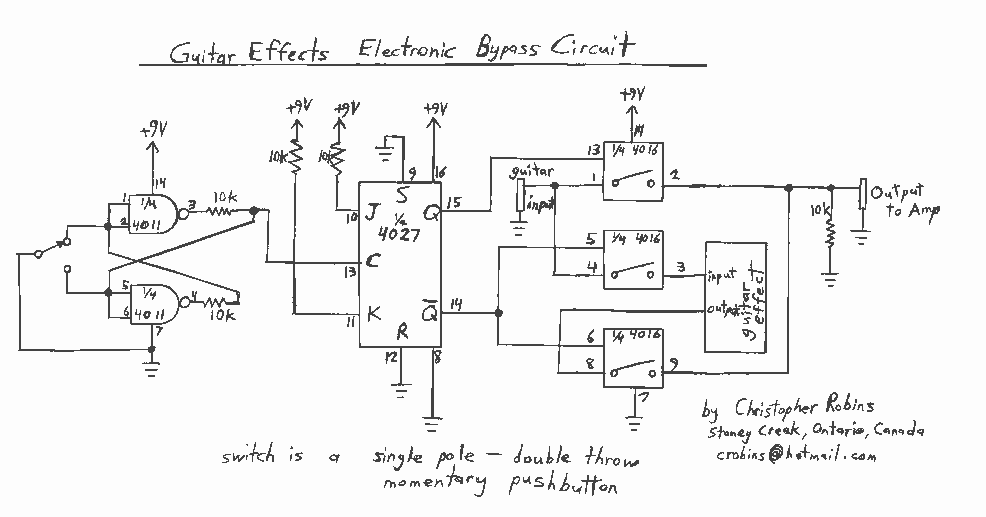
Observing my Boss pedals and how they were switched on and off I figured there must be more to it. It took me only about 4 hours to design and test this circuit. It works very well and I’m...
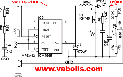
The following circuit illustrates a low voltage power supply (PSU) for Nixie tubes utilizing a 555 Timer integrated circuit (IC). The coil used in this schematic is purchased from a store. The described circuit operates as a low voltage power...
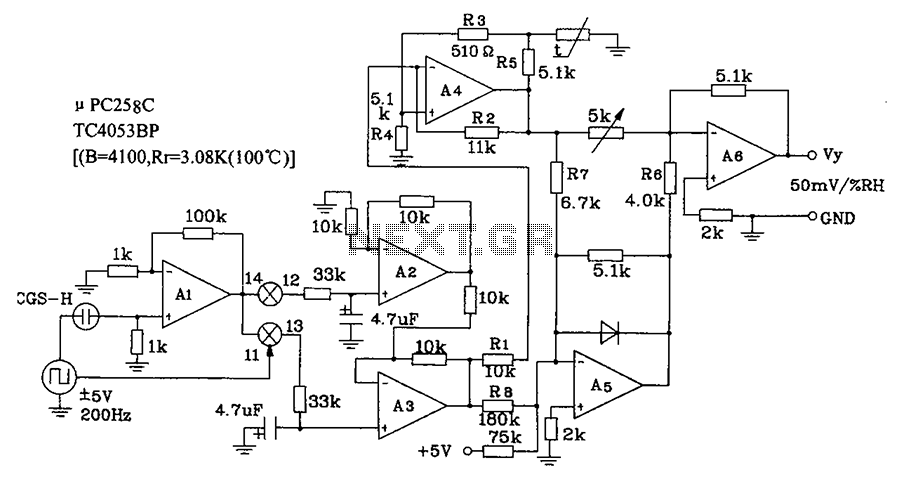
CGS-H ceramic humidity sensor constructed low humidity detection circuit diagram. The CGS-H ceramic humidity sensor is designed to detect low humidity levels within a specified range. This sensor operates on the principle of changes in capacitance that occur with variations...