
Nixie low voltage PSU With 555 Timer IC

The described circuit operates as a low voltage power supply specifically designed for Nixie tubes, which require high voltage for operation while being powered by a lower voltage source. The heart of the circuit is the 555 Timer IC, configured in astable mode to generate a pulse-width modulation (PWM) signal. This PWM output can be used to control a switching transistor or MOSFET, which in turn drives a step-up transformer or an inductor.
The circuit typically includes a few key components: a 555 Timer IC, a resistor-capacitor (RC) network for timing, a switching device (transistor or MOSFET), and a coil or transformer for voltage step-up. The RC network sets the frequency and duty cycle of the PWM signal, which is crucial for determining the output voltage and current characteristics needed for the Nixie tubes.
The power supply input is connected to a low voltage source, such as a battery or a DC power supply, usually in the range of 5 to 12 volts. The output from the transformer or coil can generate a high voltage, typically between 170 to 200 volts, necessary for the Nixie tubes to operate effectively.
In addition to the main components, it is essential to incorporate protective elements such as diodes to prevent back EMF from damaging the circuit and capacitors to filter the output voltage, ensuring stability and smooth operation. Proper heat dissipation methods must also be considered, particularly for the switching device, to prevent overheating during prolonged use.
This circuit design exemplifies an efficient approach to powering Nixie tubes, combining the reliability of the 555 Timer with the simplicity of a low voltage input to achieve the necessary high voltage output.The following circuit shows about Nixie low voltage PSU With 555 Timer IC. Features: The coil used in this schematics is bought in the shop, .. 🔗 External reference
Related Circuits
The MAX6499 includes undervoltage and overvoltage comparators for window detection. When the monitored voltage is within the selected window, the GATE is enabled. The MAX6499 is a precision voltage monitoring device designed to detect both undervoltage and overvoltage conditions within...
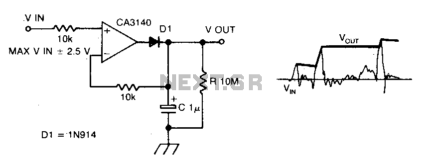
The circuit employs negative feedback exclusively for positive signals. The inverting input receives feedback only when diode D1 is forward biased, which occurs solely with positive input signals. As the positive input signal increases, the output of the operational...
The two circuits demonstrate the use of a 555 timer to activate a relay for a specified duration when a momentary normally open (N/O) push button is pressed. The circuit on the left is designed for extended time periods,...
This is a programmable clock timer circuit that utilizes individual LEDs to display hours and minutes. Twelve LEDs can be arranged in a circle to represent the twelve hours of a clock face, while an additional twelve LEDs can...
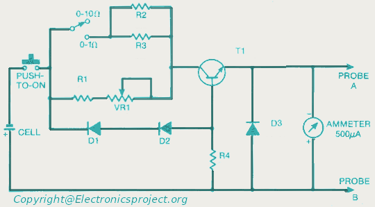
This document provides a circuit diagram for an ohmmeter designed for low resistor measurements. Additional resources, including over 300 electronic circuits, are available on this site. The ohmmeter circuit is primarily used to measure the resistance of low-value resistors, typically...
Most operational amplifier circuits require a dual-polarity power supply - one having +V and -V. However, there are times when a DP supply simply isn't conveniently available. Single-polarity modifications to DP designs often achieve their effect by referencing the...