
Passive mixer
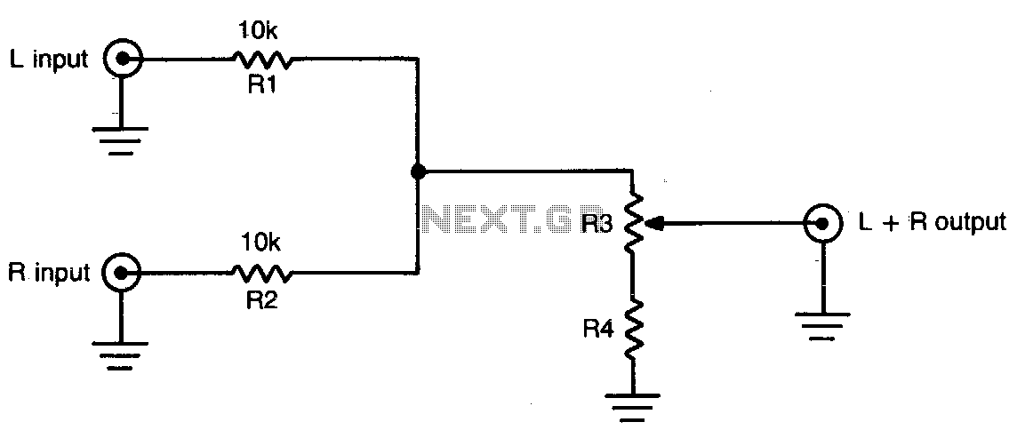
The circuit functions by taking two separate stereo input signals and merging them into a single monaural output. The primary components involved are the switch K1, resistors R2 and R3, and the input and output connectors.
K1 serves as a switch that isolates the left and right channels of the stereo input. When activated, it allows the signals from both channels to pass through while preventing interference between them. This isolation is crucial for maintaining signal integrity and ensuring that the final output is a true representation of the combined audio signals.
Resistor R2 is connected in such a way that it further isolates the two circuits, ensuring that any potential cross-talk or interference is minimized. This resistor plays a vital role in maintaining the quality of the audio output by reducing unwanted noise that can occur when combining signals.
Resistor R3 is used to adjust the level of the combined output signal. By varying the resistance, the amplitude of the output can be controlled, allowing for a balanced audio experience. This control is particularly important in applications where the output needs to match the input levels of other devices or systems, ensuring compatibility and optimal performance.
Overall, this circuit is a straightforward yet effective solution for combining stereo audio signals into a single monaural output, making it suitable for various applications in audio processing and signal routing.This simple circuit can be used to combine stereo signals to produce a monaural output K1 and R2 isolate both circuits and R3 controls the level of the combined output signal. 🔗 External reference
Related Circuits
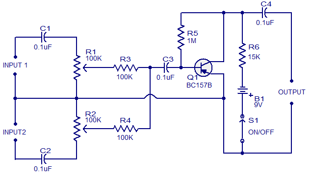
This schematic represents a low-cost microphone mixer that can be assembled using components typically found in a junk box. It is a two-channel microphone mixer designed to accommodate high-impedance dynamic microphones. Transistor Q1 can be any general-purpose PNP transistor,...
This circuit is a simple mixer circuit that can mix two signal channels into one output channel. It utilizes a codec circuit to convert stereo audio into mono audio. Additionally, the circuit can increase the number of channels by...

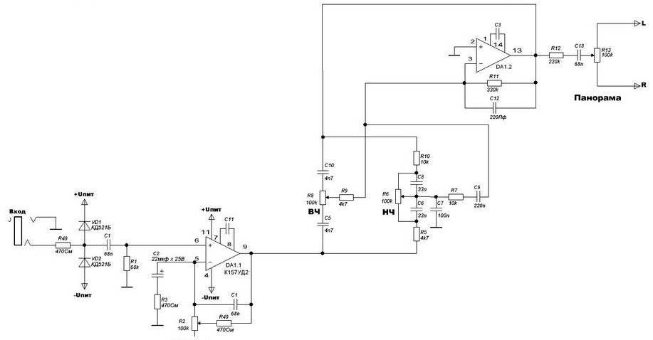
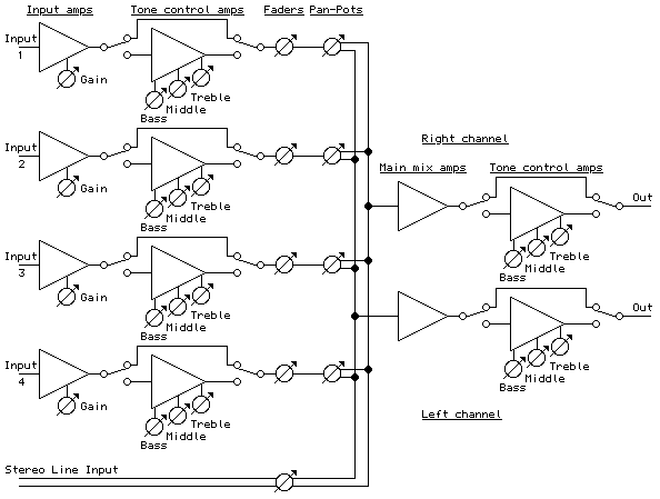
The image below depicts a block diagram of a complete mixer that consists of four input amplifier modules followed by four switchable tone management modules, one stereo line input, four mono main faders, one stereo dual-ganged main fader, four...
The four main input channels are identical and feature independently adjustable input sensitivity, tone, and sound panning. The fifth input is a linear channel. Despite its inexpensive and basic design, the Mini Audio Mixer "Impulse MM-04" performs satisfactorily. The Mini...
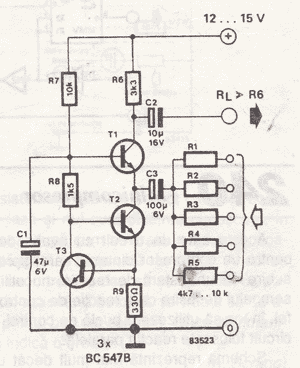
The objective of this project was to design a small portable mixer powered by a 9V PP3 battery while maintaining performance quality. The mixer consists of three main modules that can be varied in number and can be adapted...
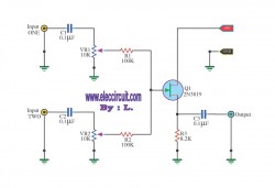
The simple mixer schematic is based on the common base principle, where input voltages are transformed into alternating currents that are summed to form the output. The simple mixer circuit utilizes the common base configuration of a transistor, which is...