
Using FET 2n3819 simple audio mixer circuit
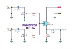
This mixer circuit is designed to combine two audio signal channels into a single mono output, making it suitable for various audio applications where space and power consumption are critical. The codec circuit serves as the primary component for converting stereo signals into a mono format, ensuring that the output is compatible with mono audio systems.
The addition of variable resistors VR1 and VR2 allows for fine-tuning of the audio levels from each input channel, providing flexibility in balancing the audio mix. Resistor R1 and capacitor C1 can be used to adjust the frequency response or gain of the circuit, depending on the specific requirements of the application. The circuit's low power consumption is advantageous for portable devices powered by 9-volt batteries, ensuring extended operation without frequent battery replacements.
When the audio signal enters the circuit, it is first coupled through capacitors C1 and C2, which serve to block any DC offset and allow only the AC audio signal to pass through. This coupling is critical in preventing distortion and ensuring that only the desired audio frequencies are processed. The signals are then directed to the variable resistors, where the user can adjust the volume levels before they reach the FET Q1.
The FET (Field Effect Transistor) Q1 acts as an amplifier, boosting the audio signal to a usable level for output. After amplification, the signal is sent through capacitor C3, which again serves as a coupling capacitor to ensure that any DC component is blocked from reaching the output stage. This final coupling stage is essential for maintaining signal integrity and ensuring that the output is clean and free from unwanted noise.
Overall, this simple mixer circuit is an effective solution for combining audio signals while maintaining low power consumption and allowing for user-adjustable audio levels. Its design is suitable for various applications, including portable audio devices, DIY audio projects, and other scenarios where space and power efficiency are paramount.This circuit, a simple mixer circuit. It can mix two signal channels and one channel is output. Using a codec circuit, Convert stereo audio to mono audio time. It can increase the number of channels too. By adding a VR1, R1 and C1 to the amount needed. Then connected to Buffett a new one. Most importantly is eating circuit current is very low. Can use with 9-volt batteries immediately. When entering voice signal, one of input 1 and input 2. Audio is via C1 and C2 of each channel, served coupling signals to VR1 and VR2. To adjust the audio to the Fet Q1. Which it serves, including audio. Then expand signal the output pin S through C3 For coupling signal again, before leaving to the output. 🔗 External reference
Related Circuits
The following circuit illustrates a timer circuit with independent mark and space periods. It is based on the 7555 integrated circuit (IC). The high output duration is calculated by T(on) = 0.7 Ra Ct, while the low output duration...
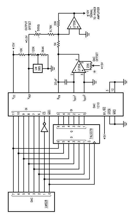
The LM628 and LM629 dedicated motion-control processors can be utilized to design various applications involving DC and brushless DC servo motors, as well as other servomechanisms. The power path of this electronic project, which functions as a motor driver,...
Logic testers are simple yet very useful devices for testing digital circuits. A logic probe can be designed in various ways. Logic testers, commonly referred to as logic probes, are essential tools in the field of digital electronics. These...
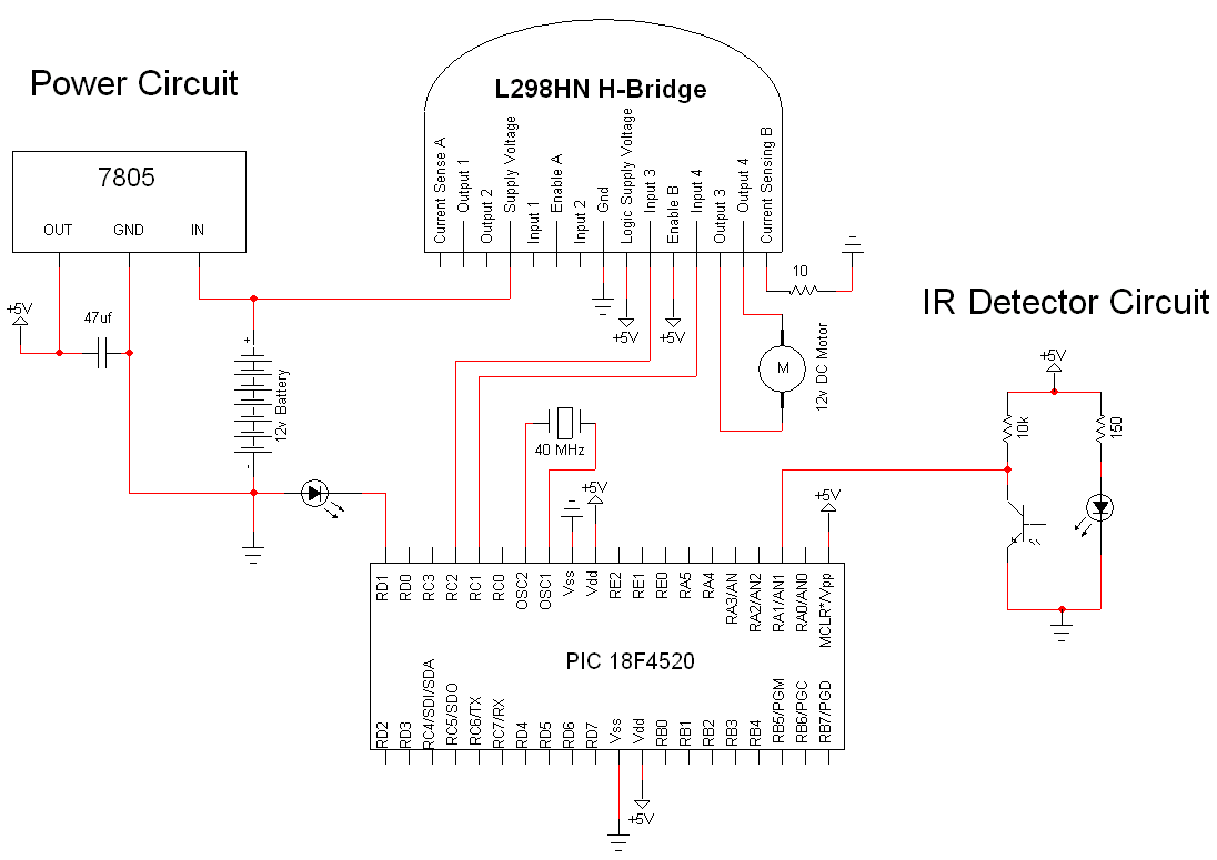
The simple motor optical encoder circuit is not particularly difficult; however, it requires careful verification to ensure all connections are correct before initial operation. The primary components utilized in the circuit include the 7805 voltage regulator, the PIC18F4520 microcontroller,...
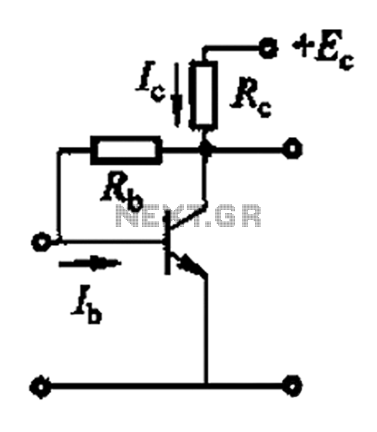
Basic reference bias circuit using a transistor with negative voltage feedback. The basic reference bias circuit utilizing a transistor with negative voltage feedback is designed to provide a stable output voltage or current that is largely independent of variations in...
Advanced power control systems utilize electronic components such as thyristors for power switching, motor control, and other applications. These systems are involved in inverter design, lamp dimming, and speed control of motors. Triacs are the most commonly used semiconductor...