
Passive tone-control circuit
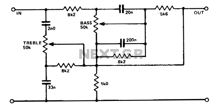
This tone control circuit typically employs two potentiometers to adjust the bass and treble frequencies of an audio signal. The configuration allows for fine-tuning of the audio output, enhancing the listening experience by allowing users to modify the tonal quality to their preference.
The circuit generally consists of two main sections: the bass control and the treble control. Each section utilizes a potentiometer connected in a voltage divider configuration. The output from each potentiometer is then fed into a summing amplifier, often implemented using an operational amplifier (op-amp). This configuration allows for the mixing of both frequency adjustments.
The potentiometers, often rated at 10kΩ, are chosen for their standard values, which are widely available and suitable for low-level audio signals. The impedance level of the circuit is designed to match that of typical low-level transistor or op-amp circuitry, ensuring compatibility and minimal signal loss.
Capacitors may also be included in the circuit to filter specific frequency ranges. For example, a capacitor can be placed in parallel with the bass potentiometer to allow lower frequencies to pass while attenuating higher frequencies. Similarly, a capacitor in the treble section can facilitate the passing of higher frequencies, enhancing the treble response.
Overall, this tone control circuit is an effective solution for audio applications, allowing for user-friendly adjustments to the tonal characteristics of the sound output while maintaining a low impedance level suitable for integration with various audio processing devices.A simple circuit using two potentiometers and easily available standard value components provides tone control. The impedance level is suitable for low-level transistor or op amp circuitry. 🔗 External reference
Related Circuits
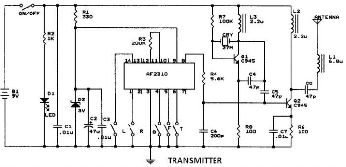
This circuit resembles that of a car radio-controlled toy with seven control functions: forward, forward-left, forward-right, backward, backward-left, backward-right, and stop. Additionally, this radio frequency circuit can be utilized for other electronic circuits that require a simple wireless motor...
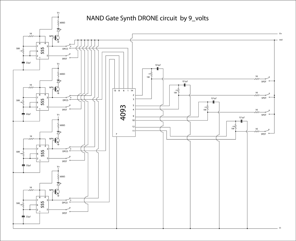
This is a brief jam session to explore the capabilities of a recently completed step sequencer. This device is quite enjoyable and expands creative possibilities. A detailed post with the circuit and instructions for building it will be provided...
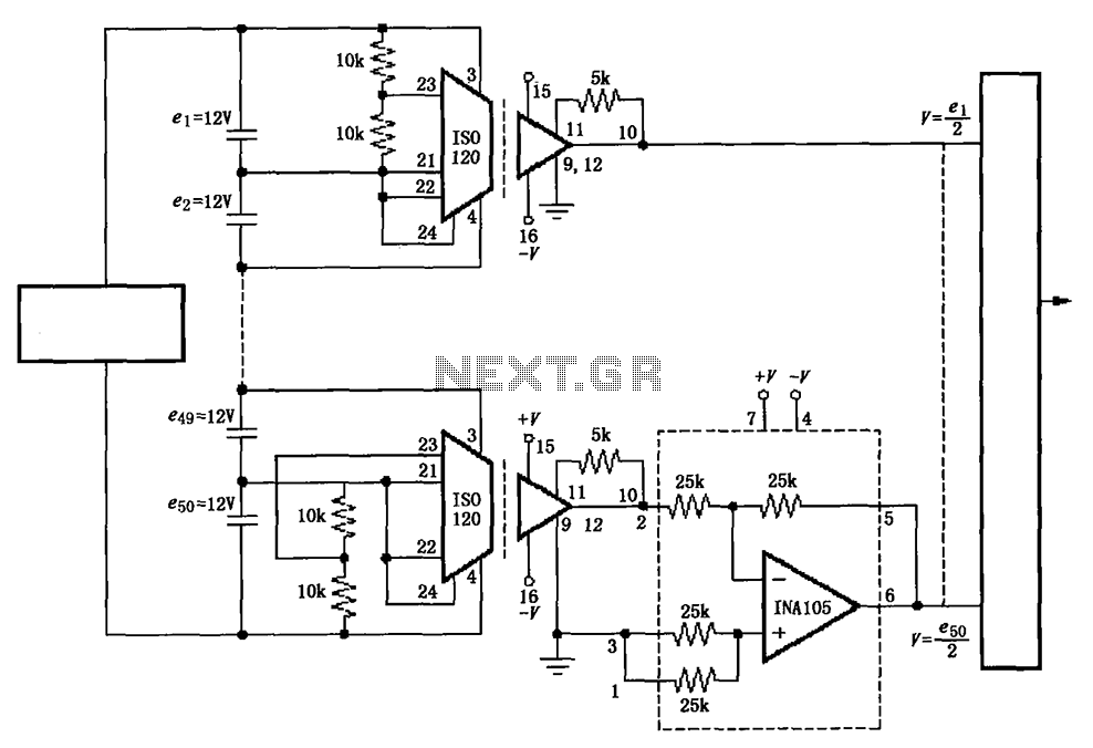
The circuit utilizes the ISO120 and INA105 instrumentation amplifiers to create a battery monitoring system for a 600V battery setup composed of 50 series-connected 12V batteries. This circuit is designed to detect charging and discharging conditions to prevent overcharging...
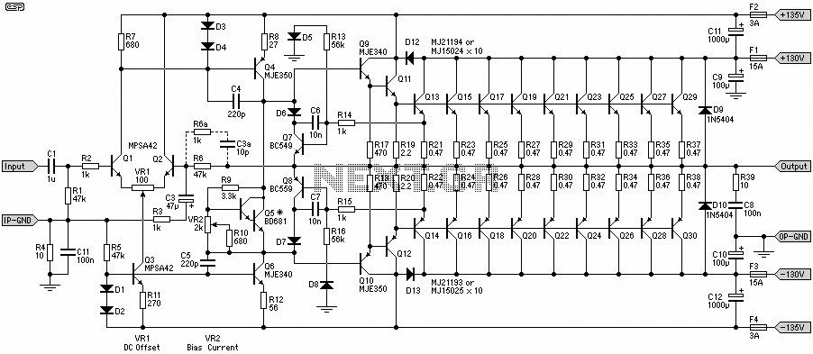
This 1500W Power Amplifier Circuit Diagram contains two images of the circuit. For more complete information, refer to the main post titled "1500 Watt Power Amplifier." It includes a list of component parts for the 1500W Power Amplifier Circuit...
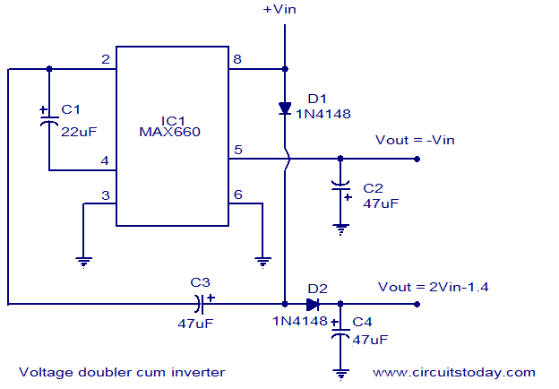
Voltage doubler circuit and voltage inverter circuit diagram with schematics using MAX660 IC, which is a DC voltage multiplier IC. This is a DC voltage doubler circuit and inverter. The MAX660 integrated circuit (IC) is designed for applications requiring a...
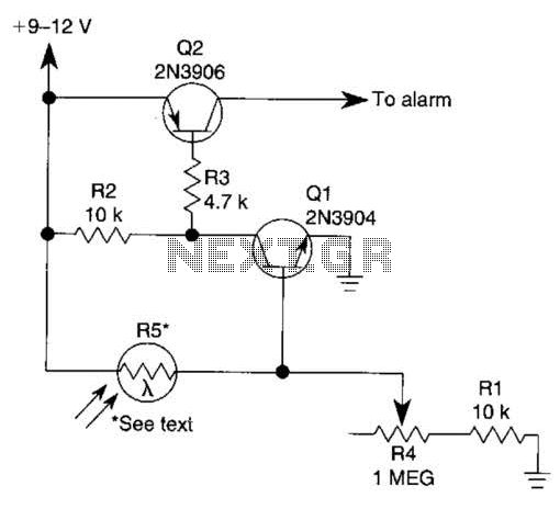
The circuit functions as a sensor capable of triggering an alarm without direct contact from an intruder. It utilizes a visible or invisible light source that illuminates the sensor, maintaining the detection loop in a normally closed state. As...