
The CDMS II Veto Readout Electronics

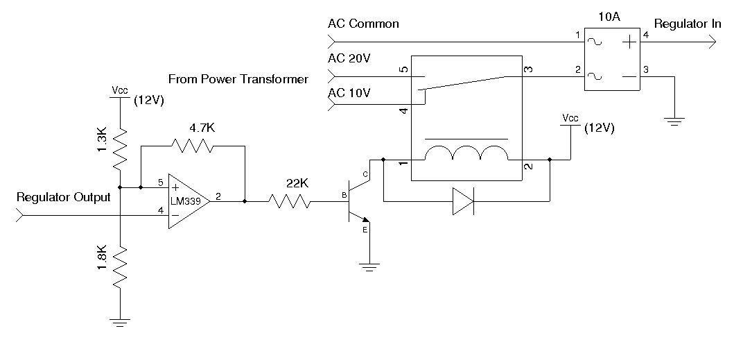
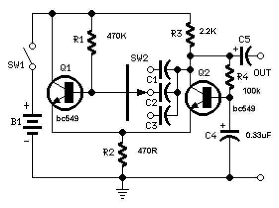
The prototype sample and hold circuit is designed to capture and retain the amplitude of input pulses that exceed a specified voltage threshold. The primary function of this circuit is to ensure that only valid pulses, which surpass the threshold of approximately 10 mV, are processed further. The circuit operates by continuously sampling the input signal using a comparator to determine when the signal exceeds the defined threshold. Upon detecting a valid pulse, the circuit engages a sample and hold mechanism that captures the peak voltage of the pulse.
The implementation of the mixed analog and digital components allows for effective integration of the sampling process with digital logic for subsequent signal processing. The analog section typically includes operational amplifiers configured as comparators and sample-and-hold circuits, while the digital section may consist of a microcontroller or digital signal processor to handle the logic and control functions.
Challenges arise due to the variable rise times of the input pulses, which can lead to inaccuracies in the captured pulse heights. This variability can introduce significant errors, particularly for input pulses that fall outside the optimal range. To mitigate these issues, careful design considerations must be made, including the selection of appropriate components that can handle the dynamic characteristics of the input signals. Additionally, implementing filtering techniques and optimizing the timing of the sample and hold circuit can enhance performance and accuracy.
Overall, this prototype serves as a foundational circuit for applications requiring precise pulse height measurements while highlighting the importance of addressing rise time variability to improve reliability across a broader range of input conditions.A Prototype Sample and Hold Circuit -The original idea for the veto front end amps was to continually sample the input pulse height and hold the pulse height for any pulses passing a low voltage threshold (~10mV). This mixed analog and digital circuit was actually made to work. Unfortunately, the highly variable risetimes of the input pulses cause d large pulse height errors for all but a very limitied range of input pulse heights. 🔗 External reference
Related Circuits
The April 1955 issue of Popular Electronics magazine features a cover illustration of a gentleman playing a homebuilt Theremin. Theremins are among the earliest electronic musical instruments, invented in the 1920s by Russian inventor Leon Theremin. The instrument is...
A used 250VA power transformer has been removed from equipment recently. The transformer features a dual 10V AC output along with several auxiliary voltage outputs. The 10V winding is rated for 10A, making it suitable for a high current...
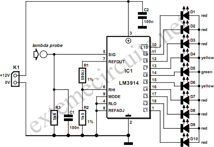
A lambda probe, also known as an oxygen sensor, is typically located on the exhaust system of most vehicles that operate on unleaded fuel. It functions effectively once it has reached its normal operating temperature. A lambda probe is a...
Acquire all the components required for this lecture here. It is highly recommended to obtain a multimeter with a continuity setting. A quality multimeter with this feature typically costs around $60, while premium models can reach $300. The $60...
A useful feature of this circuit is that the frequency can be changed by modifying the capacitor value. A switch can be added to select between various frequencies. This circuit utilizes a capacitor in conjunction with an oscillator to determine...
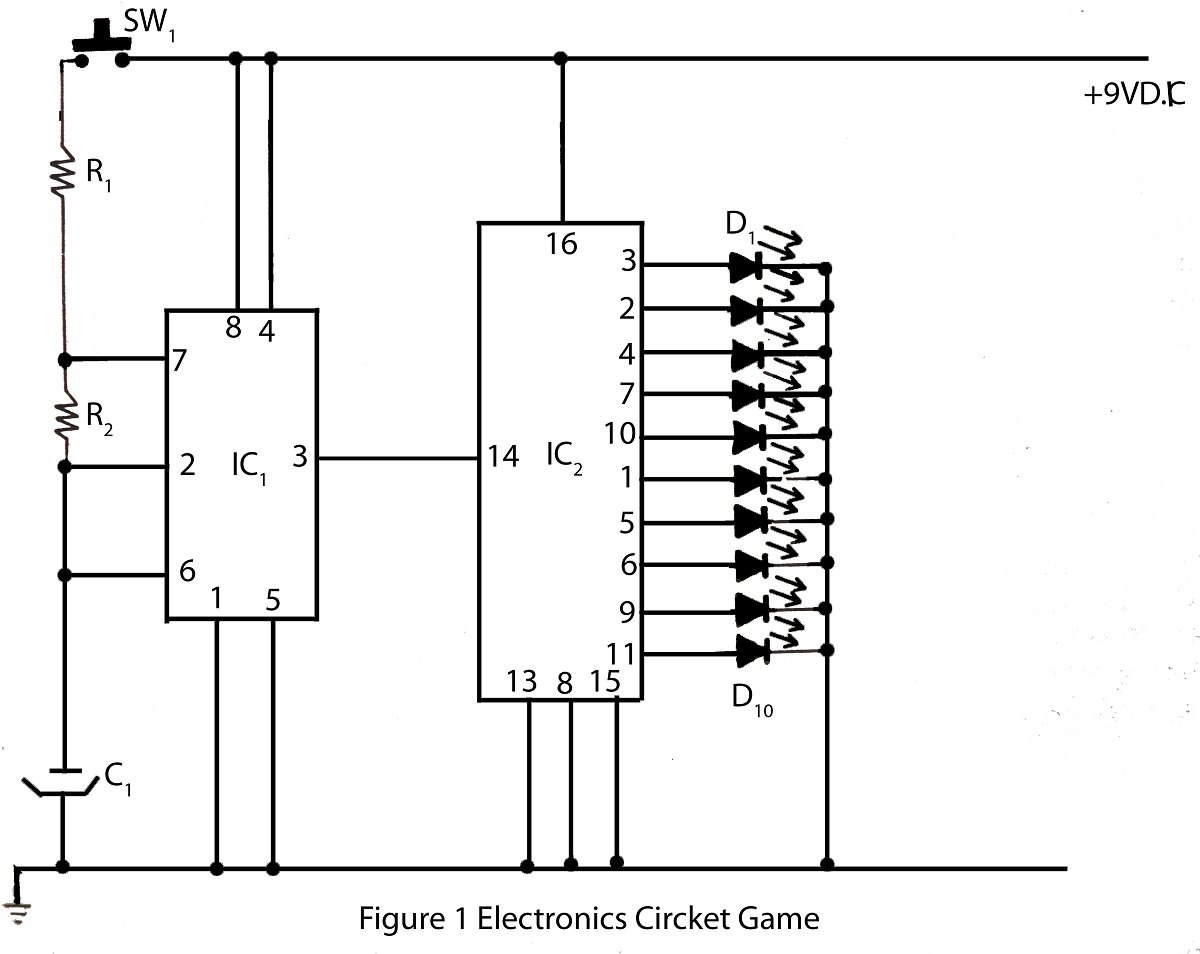
The electronics cricket game circuit presented on this website is a straightforward and easy-to-build circuit diagram for an electronics cricket project, as well as various other game projects. The electronics cricket game circuit typically consists of several key components that...