
TDA0161 metal detector electronic schematic

The TDA0161 integrated circuit is central to the operation of this metal detector. It operates by generating a high-frequency signal that induces Eddy currents in nearby metallic objects. As these currents circulate, they produce their own magnetic fields, which the circuit detects as variations in the original signal. The sensitivity of the circuit can be adjusted to accommodate different types of metals and their distances from the coil.
The circuit design includes a power supply that stabilizes the voltage, ensuring consistent performance regardless of fluctuations in input power. The two LEDs serve as indicators: one LED lights up when metal is detected, while the other may indicate a lack of detection. This dual-indicator system allows for easy interpretation of the circuit's status.
Calibration of the metal detector is crucial for optimal performance. The initial step involves ensuring that the vicinity of the coil is free from metallic interference. Setting the fine adjustment to the mid-position provides a baseline for further adjustments. The coarse adjustment is then used to activate the LED, indicating that the circuit is responsive to metal detection. Finally, the fine adjustment is utilized to turn off the LED, confirming that the circuit is correctly calibrated to ignore background noise and only respond to significant metallic objects.
Overall, this metal detector circuit is a practical application of the TDA0161 IC, demonstrating effective detection capabilities through a straightforward calibration process and visual feedback via LED indicators.This metal detector circuit diagram is based on the TDA0161 monolithic integrated circuit, designed for metallic body detection by detecting the variations in high frequency Eddy current losses. Output signal is determined by supply current changes. Independent of supply voltage, this current is high or low according to the presence or the absenc e of a close metallic object. Using two LEDs this circuit provide an visual indication of presence or absence at a metals around the coil. To adjust the circuit you need to make sure there is no metal near the coil and then set the fine adjustment to a "Mid position".
After that you need to adjust the course adjustment to turn on the LED and, adjust the fine adjustment to turn off the LED. 🔗 External reference
Related Circuits

The oscillator generates a 1 MHz and a 1 kHz clock signal. The 1 MHz clock serves as the primary clock for the microcontroller and provides a time base for millisecond measurements. A 2 MHz signal is divided by...

A simple metal detector electronic project circuit can be designed using the CS209A integrated circuit manufactured by Cherry Semiconductor. The CS209A integrated circuit is a bipolar monolithic integrated circuit intended for metal detection and proximity sensing applications. It incorporates...

A tone control or pre-amplifier is an amplifier circuit that enhances audio signals. It is important to understand the characteristics, advantages, and disadvantages of various amplifier equipment, as the performance of different amplifiers may not show significant differences. The...

This circuit utilizes the operational amplifier IC LM324 to drive the VN64GA with an error signal and to regulate the output voltage. The output voltage generated is pulsating DC, which is suitable for battery charging applications. Additionally, this circuit...
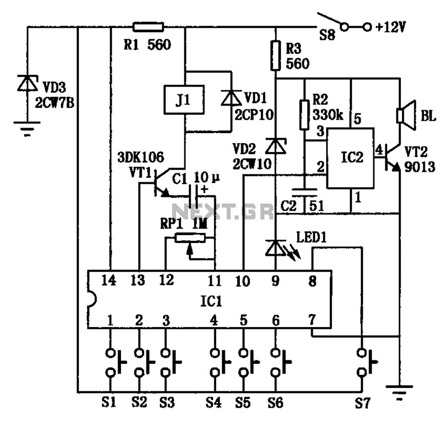
The automotive electronic locks circuit principle is illustrated with the dedicated lock IC 5G058. It features an external key switch connected to the positive power supply. The circuit includes six valid input keys, unlock keys S1 to S6, which...
The Elect. Sel. 8 is a simple circuit, with a choice of 8 sources of any sort, of 8 independent switches. Each switch corresponding with a relay for example the switch S1 activates the RL1 etc. The uses of...