
Zener Diode Tester

The circuit utilizes a 555 Timer IC configured in astable mode to produce a square wave output. The frequency of oscillation is determined by the resistor and capacitor values connected to pins 6 and 2 (threshold and trigger) and pin 3 (output). The output pulse from pin 3 is fed into the primary winding of a small audio transformer, such as the LT700. This transformer has a primary impedance of 1K ohm and a secondary impedance of 8 ohms, allowing it to step up the voltage significantly.
When the circuit is powered, the 555 Timer generates an alternating voltage at the output, which induces a high voltage in the secondary winding of the transformer. The unloaded AC voltage can reach approximately 120 volts AC, which is suitable for testing zener diodes with voltage ratings up to 50VDC.
The AC output is then rectified using a 1N4004 diode, which is a general-purpose silicon rectifier capable of handling the required current and reverse voltage. Following the rectification, a smoothing capacitor of 2.2uF is connected to filter the output, ensuring that the voltage presented to the zener diode is stable. It is crucial that this capacitor is rated for at least 150 VDC to prevent breakdown and ensure reliability during operation.
For testing purposes, the zener diode under examination is connected in parallel with the output of the circuit. A multimeter set to measure DC voltage is used to assess the voltage across the zener. Additionally, a load current switch is incorporated to allow the user to select between testing the zener at a load of 1 mA or 2 mA DC, facilitating a more accurate assessment of the zener's breakdown voltage and performance characteristics under specified conditions. This circuit provides a practical means of testing zener diodes effectively while ensuring safety and reliability.Using a single 555 Timer IC and a small transformer to generate a high voltage, this circuit will test zener diodes of voltage ratings up to 50VDC. The 555 timer is used in the astable mode, the output at pin3 drives a small audio transformer such as the LT700.
This has a primary impedance of 1K and a secondary impedance of 8 ohms. Used in reverse the unloaded ac voltage is around 120volts ac. This is rectified by the 1N4004 diode and smoothed by the 2.2u capacitor which MUST be rated at 150 VDC. The zener under test is measured with a multimeter set to DC volts as shown. The load current switch enables the zener to be tested at 1 or 2mA DC. Th 🔗 External reference
Related Circuits

This circuit is designed to test zener diodes. It connects to a 120V AC line and amplifies the output. The zener diode testing circuit operates by utilizing a transformer to step down the 120V AC line voltage to a more...
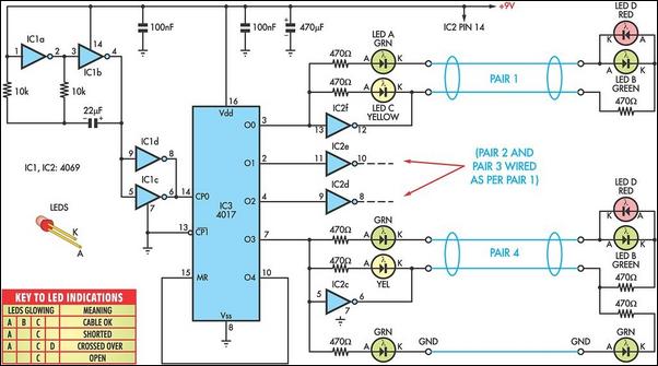
You do not need access to advanced testing equipment to check and troubleshoot computer data cables. Instead, this simple device will provide a quick indication of the status. This device functions as a basic cable tester, designed to assess the...
This digital thermometer circuit diagram utilizes a standard 1N4148 diode as the temperature sensor. The temperature coefficient of the diode is -2 mV/°C. The digital thermometer circuit leverages the characteristics of the 1N4148 diode, which exhibits a predictable voltage drop...
If you want to test an amplifier, a dummy load may be more convenient for speakers to use than actual speakers, due to noise or damage to the speakers. This circuit behaves in terms of impedance and frequency response...
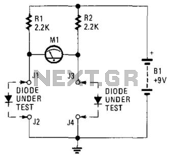
This circuit can be utilized to match diodes for applications where balance is essential, such as in a balanced modulator. The diode matching circuit will display the forward voltage drop of the two diodes in millivolts. The diode matching circuit...
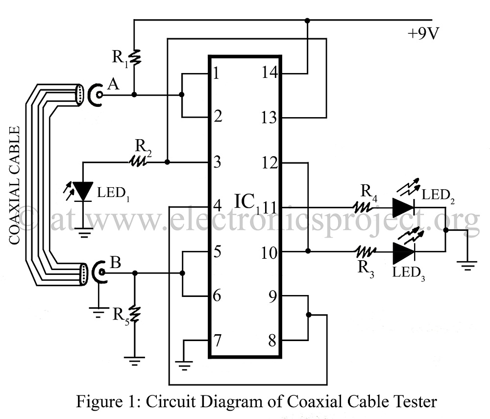
A coaxial cable tester is utilized to determine the condition of a coaxial cable, identifying whether it is open, short-circuited, or functioning correctly. This device employs a digital IC 4001 and includes a circuit description along with a parts...