
Continuity And Component Tester
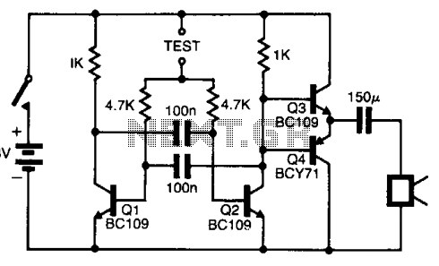
The continuity tester is a simple yet effective tool used to check the integrity of electrical connections and circuits. The primary function of this device is to provide an audible indication when a closed circuit is detected, signaling that current can flow between the two probes. The schematic diagram typically includes a power source, such as a battery, a resistor, a diode, and a piezoelectric buzzer or speaker to produce the sound.
In the schematic, the battery serves as the power supply, providing the necessary voltage to the circuit. The probes are connected to the circuit, and when they touch a conductive path, an electric current flows through the circuit. This current passes through a resistor, which limits the current to a safe level for the buzzer.
The diode may be included to protect the circuit from reverse polarity, ensuring that the current only flows in one direction. When the probes are connected, the current activates the piezoelectric buzzer, producing a beep sound that indicates continuity.
The design of the continuity tester is straightforward, making it accessible for both professional and amateur electronics enthusiasts. The components can be easily sourced, and the circuit can be assembled on a breadboard or printed circuit board (PCB) for more permanent applications.
This device is essential in various applications, including troubleshooting electrical systems, verifying connections in wiring, and ensuring that circuit paths are complete before powering up devices. Overall, the continuity tester is a valuable tool in the field of electronics, providing immediate feedback on circuit integrity.This continuity tester gives a beep sound if detect an electric current conduction between its probes. Here is the schematic diagram of this audible.. 🔗 External reference
Related Circuits
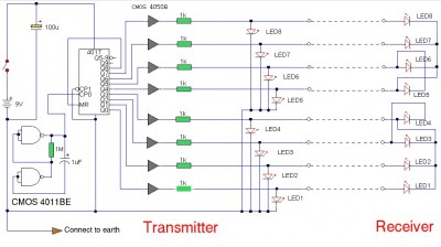
The LAN tester circuit can also test cables such as telephone, coaxial, LAN, and others. This circuit uses LEDs as the main indicator device. The LAN tester circuit is designed to verify the integrity and functionality of various types of...
Tests 1.5 to 15 Volt cells. This circuit runs a fast battery test without the need of power supply or expensive moving-coil voltmeters. It features two ranges: when SW1 is set as shown in the circuit diagram, the device...

This circuit is designed to detect the approximate percentage of salt contained in a liquid. After careful calibration, it provides a quick, rough indication of the salt content in liquid foods for dietary purposes. The circuit utilizes the LM324...
A quartz crystal tester is required to determine the functionality of a crystal, indicating whether it is operational or defective. This tester features an LED light indicator. A quartz crystal tester is an essential tool for evaluating the condition of...
The pitch of the tone is dependent upon the resistance under test. The tester will respond to resistance of hundreds of kilohms, yet it is possible to distinguish differences of just a few tens of ohms in low-resistance circuits....
For individuals who prefer not to engage directly with soil, this simple soil moisture tester efficiently assesses the condition of their plants and the level of care they require. The soil moisture tester is a device designed to measure the...