
2 channel audio mixer circuit using transistors
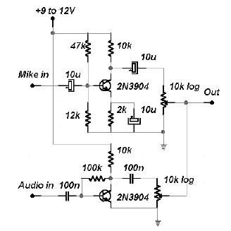
This two-channel audio mixer circuit is designed to enhance audio signals through the use of bipolar junction transistors (BJTs), specifically the 2N3904 model. The circuit comprises two distinct preamplifier stages, each tailored for specific audio signal types.
The first preamplifier stage is optimized for microphone inputs, providing significant gain to ensure that low-level audio signals from dynamic microphones are amplified sufficiently for further processing. This stage typically includes resistors and capacitors configured to set the gain and frequency response, ensuring clarity and fidelity in the amplified signal.
The second preamplifier stage is designed to manage the audio levels from various sources such as CD players and MP3 players. This stage incorporates a variable resistor (potentiometer) to allow users to adjust the input level dynamically. This feature is crucial for mixing audio from different sources, enabling a balanced output that can be tailored to the desired audio experience.
The power supply for the audio mixer is critical, requiring a stable voltage between 9 to 12 volts. This voltage range ensures that the transistors operate efficiently, maintaining linearity and minimizing distortion in the amplified audio signals.
Connections for the audio inputs are typically made through 1/4 inch or RCA connectors, allowing compatibility with a wide range of audio devices. The output from the mixer can be directed to amplifiers or recording devices, making it versatile for both live sound applications and studio environments.
Overall, this audio mixer circuit is an effective solution for managing and amplifying audio signals from multiple sources, making it suitable for various audio applications, including home studios, live performances, and other audio mixing scenarios.This 2 channels audio mixer is based on the 2n3904 transistors which forms 2 preamplifiers. The first preamplifier of the audio mixer has a high gain and can be used for microphone input, and the second one can be used to control the input of the audio level. This two channel audio mixer require a power supply with the output voltage between 9 to 12 volts. For the audio signal you can use a CD player, mp3 player or other audio device and for the microphone you can use a normal dynamic microphone. 🔗 External reference
Related Circuits
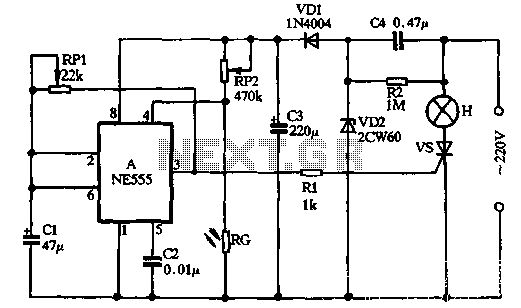
VDI, VD2, C3, and C4 form a simple half-wave rectifier capacitor step-down regulator circuit. This circuit can output approximately 12V DC voltage after power is applied across C3, which is utilized for the time base circuit. Additionally, the time...
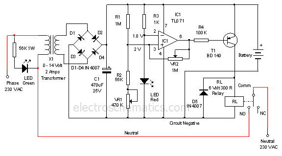
This is a 12-volt lead-acid automatic battery charger that stops the charging process once the battery reaches a full charge. This feature prevents overcharging. The 12-volt lead-acid automatic battery charger is designed to efficiently charge lead-acid batteries while ensuring safety...
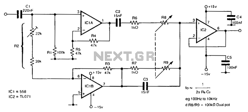
The circuit utilizes a single dual-ganged potentiometer to achieve tuning across a broad spectrum, potentially covering the entire audio range in a single adjustment. The underlying principle is based on the Wien bridge configuration, which is supplied with anti-phase...
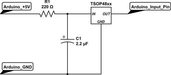
To set up the circuit, a resistor is required; a value of 200 Ohms is suggested, with a supply voltage of 3.3V. The resistor should be connected to the power line and grounded. The data line must be connected...
A rear fog lamp is mandatory for trailers and caravans to enhance visibility during foggy conditions. When the fog lamp is activated, the fog lamp of the towing vehicle must be turned off to prevent distracting reflections. To achieve...
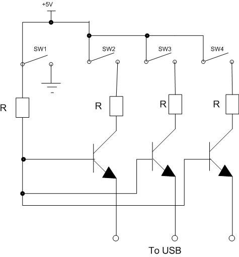
Four switches will be connected to a USB joystick board. The USB board has +5V and ground connections and emulates a button press. The circuit involves interfacing four mechanical switches with a USB joystick interface. The USB joystick board typically...