
light activated relay
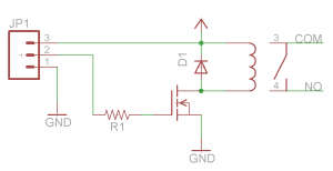
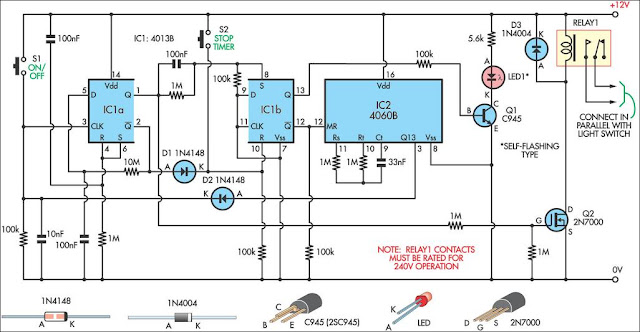
The described circuit utilizes a flip-flop configuration, which serves as a bistable multivibrator. This allows the circuit to maintain a state until an external trigger is applied. In this case, the triggering mechanism is a photoresistor (LDR), which changes its resistance in response to varying light levels. The inclusion of a bias resistor in series with the photoresistor is crucial for establishing the correct operating conditions for the 2N3904 NPN transistor.
The 2N3904 is chosen for its ability to handle moderate current levels and its suitability for switching applications. The bias resistor must be calculated to ensure that the base-emitter junction of the transistor is forward-biased when the light intensity reaches a certain threshold. This threshold is determined by the characteristics of the photoresistor and the environmental lighting conditions.
When the circuit is exposed to a sudden increase in light intensity, such as from a flashlight beam, the resistance of the photoresistor decreases, causing an increase in voltage at the base of the 2N3904. This results in the transistor turning on and allowing current to flow through the collector-emitter path, thus toggling the flip-flop state. Conversely, if the light intensity decreases gradually, the circuit remains unaffected until the light becomes bright enough to alter the bias condition of the transistor.
In summary, this circuit effectively uses a photoresistor for light-sensitive triggering of a flip-flop, providing a novel approach to light-activated switching applications. Proper selection of component values, particularly the bias resistor, is essential for the reliable operation of the circuit under varying ambient light conditions.This is same circuit as above with the addition of a photo resistor to trigger the flip flop instead of a push button. The bias resistor in series with photo resistor was chosen so that sufficient voltage is present at the base of the 2N3904 to supply current to the circuit in ambient lighting conditions.
The circuit should toggle when the photo r esistor is hit by a flashlight beam or other fast changing light source. Slow changes in light intensity will have no effect unless the light gets too bright to maintain sufficient bias for the 2N3904. 🔗 External reference
Related Circuits
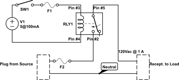
Before proceeding with the toaster oven reflow oven project, it is essential to understand the operation of relays and how to construct a simple relay breakout board. This discussion will focus on the design of a relay breakout board...

This light dimmer control features active timing capacitor reset or AC line zero-crossing synchronization. The 13 additional components are common and cost less than $2. Performance at the low end is exceptionally smooth and snap-free, even better than the...
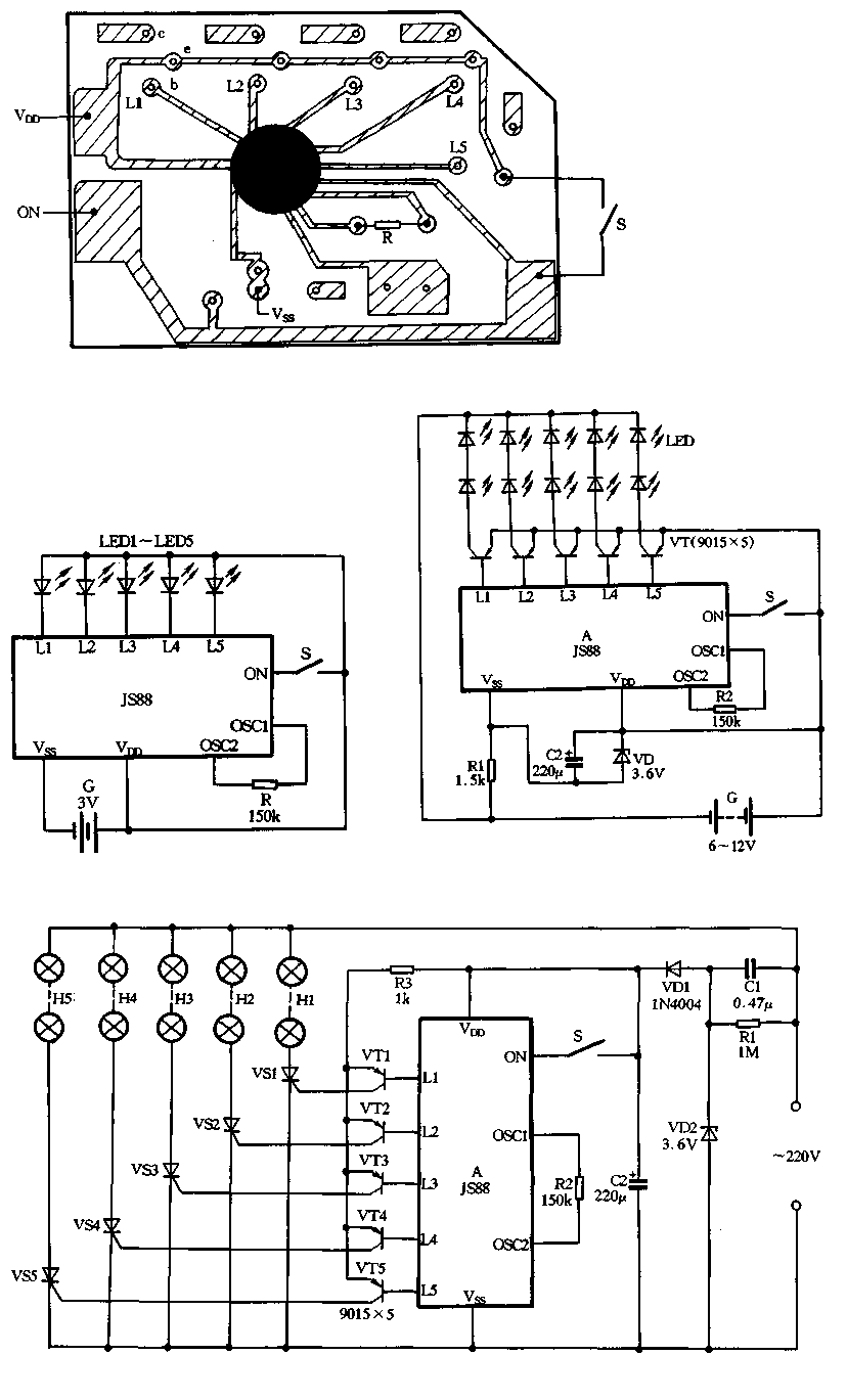
Figure 2-39 illustrates a typical application circuit for the JS88 manifold, which includes an oscillation resistor (R) that allows for fine-tuning of the water flicker frequency. When switch (S) is closed, components L1 to L5 sequentially output low signals...
This is a minimal circuit designed for individual audio amplifier projects to control the presenter output relay. The purpose of this circuit is to manage the relay that activates the speaker output within the audio amplifier. The circuit introduces...
This 9-minute timer switch is designed to control lighting in a toilet or bathroom. The timer is activated by pressing switch S1 and deactivated by pressing S1 again. If the switch is not turned off, the light will automatically...
A single-pole double-throw (SPDT) switch is used to control a relay. When the relay is energized, it produces a cycling sound, which is undesirable. The goal is to have the switch operate normally in the 'on' position and return...