
Chandelier Dimmer

The chandelier dimmer circuit allows for the adjustment of light intensity in chandeliers, enhancing the ambiance of a space. The design typically includes a dimmer switch that can be installed in place of the standard pull cord switch. This switch can be a rotary, slide, or touch-sensitive type, depending on user preference and design requirements.
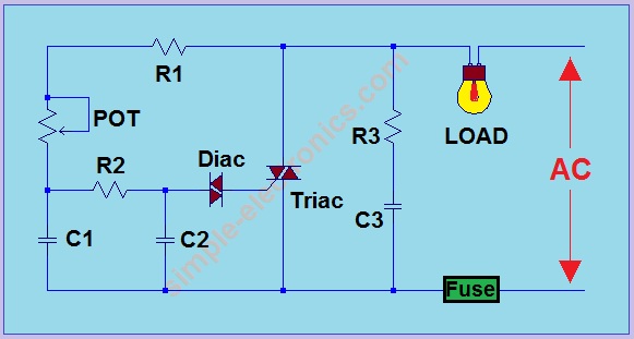
The circuit consists of several key components: a dimmer switch, a microcontroller (optional for smart features), a triac for controlling the power delivered to the lamps, and appropriate resistors and capacitors for filtering and stability. The dimmer switch modifies the phase of the AC signal, effectively reducing the power supplied to the lamps, which in turn dims the light output.
In the case of a pull cord switch, the installation of a dimmer requires careful consideration of the existing wiring. The small wire mentioned in the description could serve as a control line, allowing the dimmer to communicate with the microcontroller or other smart home devices, enabling features such as remote control or programmable lighting scenarios.
Safety considerations must also be addressed, including ensuring that the dimmer is rated for the total wattage of the chandelier and that all connections are secure and insulated to prevent short circuits. Additionally, the dimmer should comply with local electrical codes and standards to ensure safe operation.
Overall, the integration of a dimmer into a chandelier not only enhances aesthetic appeal but also adds functionality, allowing for customizable lighting experiences.Chandelier Dimmer , Many of the chandeliers have a pull chord switch. Now add a novelty to your chandelier and surprise the guests. Place a small wire down the lamps from.. 🔗 External reference
Related Circuits
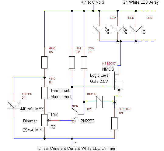
This simple linear circuit provides continuously variable regulated current (~25-400mA) from a 4-6 Volt source. The linear design is chosen for simplicity, reliability, ease of repair, and to avoid switching EMI in cave radios. The circuit requires only 0.2V...
The circuit was designed to create a lamp that incorporates the operation of a touch dimmer using the S566B integrated circuit manufactured by Siemens. The circuit utilizes the S566B IC, which is specifically designed for touch-sensitive applications, to enable a...

A project is underway to create a custom electronic circuit for a 1969 Chevelle. The design aims to replicate a retained accessory power feature similar to a product offered by Dakota Digital, but at a lower cost. The circuit...

This is a design circuit for a soft light dimmer. The circuit utilizes the IGBT STGP10N50A and the TS555 timer as the main components. The timer is triggered by the zero crossing voltage pulse. The time constant, determined by...

A full range power controller suitable for lamp dimming and similar applications operates from a 120-volt, 60 Hz AC source and can control up to 1000 watts of power to incandescent bulbs. The power to the bulbs is varied...
Note: Do not build or use this if you do not have any knowledge in electrical or electronics. This project is not safe for beginners, and the voltage involved is dangerous and can cause electrocution. Do not exceed the...