
fm radio receivers
An AM receiver circuit typically includes several key components: an antenna, a radio frequency (RF) amplifier, a mixer, a demodulator (or detector), and an audio amplifier. The antenna captures the AM broadcast signal, which is then amplified by the RF amplifier to improve the signal strength and reduce noise. The amplified signal is fed into a mixer, where it is combined with a local oscillator signal to produce an intermediate frequency (IF) signal. This IF signal is easier to process and filter.
The demodulator is a crucial component of the AM receiver, responsible for extracting the audio information from the modulated carrier wave. A common type of demodulator used in AM receivers is the envelope detector, which utilizes a diode to rectify the incoming signal. The diode allows current to flow only during the positive half-cycles of the AM signal, effectively removing the negative half-cycles and creating a varying voltage that corresponds to the original audio signal. A capacitor is typically used in conjunction with the diode to smooth the output, filtering out high-frequency components and leaving the audio signal intact.
After demodulation, the audio signal may still contain some noise and distortion. Therefore, it is sent to an audio amplifier, which boosts the signal to a level suitable for driving speakers or headphones. The audio amplifier may include additional filtering stages to further reduce noise and improve sound quality.
In summary, the AM receiver circuit efficiently converts amplitude-modulated signals into audible audio signals while addressing challenges such as noise and distortion. The evolution of AM technology has paved the way for more advanced modulation techniques like FM, which offer improved sound quality by varying the carrier frequency instead of amplitude.An AM receiver relies upon the original carrier signal (station frequency) having been amplitude modulated. This means the original amplitude (strength) varies at an audio rate. Looking at figure 1 we can see an unmodulated carrier signal as it might be seen on an oscilloscope. as you can see the amplitude of the carrier signal is unvarying, it remains constant in height looking
from the top of the figure to the bottom of the figure. This carrier is common to both a. m. and f. m. signals. Perhaps the a. m. carrier signal repeats each cycle from point (a) to point (b) - "blue" - in figure 2 below at the rate of 810, 000 times a second, this represents a frequency of 810 Khz and would be in the a. m. radio band. Here you will notice that the audio modulating signal which is depicted in red has varied the strength of the carrier signal which is depicted green for purposes of this illustration.
You will note my skills as a graphic artist leave much to be desired (hint: anyone able to contribute oscillograghs in. jpg or. gif formats ) but you should be able to see the carrier sine wave envelope is being varied in strength by the red audio signal.
In the receiver circuit a diode detector can convert that envelope above back into the original audio signal for later amplification although some distortion does result. It was to an extent this distortion property that people sought a better means of transmission. More important it was discovered that noise (either man made QRM or natural noise QRN) was amplitude in its properties.
I have depicted two blue lines in the diagram above, these represent noise impulses caused perhaps by automobile ignition, nearby fluorescent lighting, your computer or atmospheric noise such as a distant storm. Note the blue lines extend beyond the amplitude envelope, they could be many times the magnitude of the received signal.
For these reasons frequency modulation evolved. Instead of varying the amplitude of the carrier signal, which remains constant, we vary the carrier frequency more or less by the audio frequency. 🔗 External reference
Related Circuits
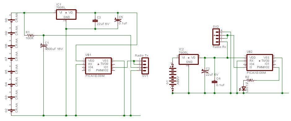
A water tank, dam, or gate can be monitored for vehicle detection without the need for wired connections through the garden. This guide demonstrates how to transmit data reliably over a distance of 500 meters using PICAXE microcontroller chips...
This circuit illustrates the BF495 transistor used in an AM transmitter radio circuit diagram. Features include a powerful AM transmitter utilizing ceramic components. The BF495 transistor is a high-frequency NPN transistor commonly used in RF applications, including AM transmitters. In...
The AM radio receiver circuit diagram is based on the single integrated circuit MK484. The components list includes: R9, R10 (6.8 ohms), R6 (100 ohms), R3 (1k ohms), R1 (4.7k ohms), R7 (5.6k ohms), R4 (10k ohms), R2 (100k...
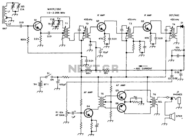
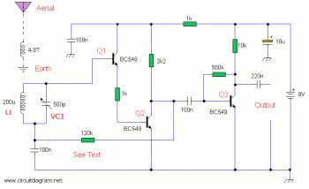
A schematic of a typical transistor AM radio is presented. This circuit utilizes npn transistors. It is a generic circuit; hence, specific values for some components are not provided. This circuit serves as a reference point for experimenters. The schematic...
The performance indices of the telecontrol receiving decoding circuit are as follows: radio frequency (f) = 27 MHz, audio frequency (f) = 5.5 kHz, 100% modulation in square-wave form; radio frequency deviation is ±600 Hz, and the frequency shift...
This schematic illustrates a high-quality AM radio receiver circuit centered around the MK484 AM radio integrated circuit (IC). The MK484 is known for its high sensitivity and superior performance, featuring only three leads and housed in a TO-92 package....