
PC IR Remote Control Hardware

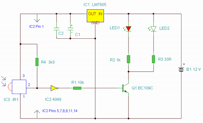
The described hardware system consists of two primary modules: a signal capture module and a transmission module. The signal capture module is responsible for detecting and processing incoming signals, which may include timing functions necessary for synchronization with the target equipment. This module typically incorporates components such as operational amplifiers for signal conditioning, analog-to-digital converters (ADCs) for digitizing the signals, and microcontrollers for processing the captured data and executing timing functions.
The transmission module is designed to send processed signals to the target equipment. It is strategically placed near the equipment to ensure effective communication. This module may include a digital-to-analog converter (DAC) if the output needs to be in analog form, as well as RF transmitters or other communication interfaces depending on the requirements of the target system.
Communication between the hardware modules and the IBM compatible PC is established through the printer port, specifically utilizing the "Paper Tray Empty" and "Printer Busy" pins for input. These pins serve as digital input signals that can be monitored by the microcontroller within the signal capture module. The Data lines 0 and 1 are utilized for output, allowing the system to send data back to the PC for further processing or display.
The overall design should ensure that signal integrity is maintained throughout the system, with appropriate filtering and shielding to minimize noise and interference. Power supply considerations are also critical, as both modules must be adequately powered while ensuring that the voltage levels are compatible with the interfacing components of the PC. Proper grounding and circuit layout techniques should be employed to enhance reliability and performance.The hardware (as I have bullt it) is constructed from two modules, one to capture the signal and provide timing functions, and the second as transmitter placed somewhere near the target equipment. I have interfaced this to my IBM compatible PC on the printer port, using the two pins "Paper Tray Empty" and "Printer Busy" as input, and Data lines 0 and 1 as output.
🔗 External reference
Related Circuits
This is an enhanced infrared (IR) remote control extender circuit. It features high noise immunity, resistance to ambient and reflected light, and an increased operational range. The improved IR remote control extender circuit is designed to extend the range of...
This shows the overall circuit diagram of the power control unit. On the left, there is a main relay controlled by the key switch. The power control unit circuit diagram illustrates the primary components and their interconnections for managing electrical...
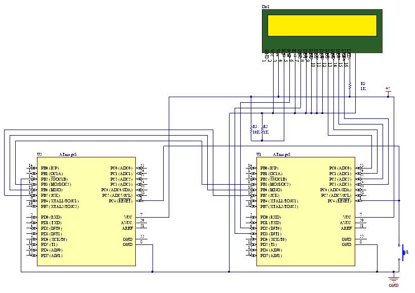
This document outlines the process of transmitting data between a PC and an AVR Atmega8 microcontroller using the USART module. The communication utilizes the COM port of the PC, which is based on the RS232 protocol, and the UART...
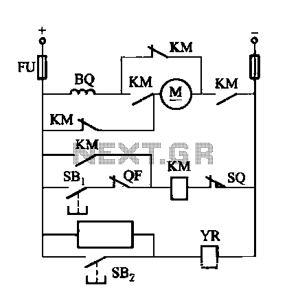
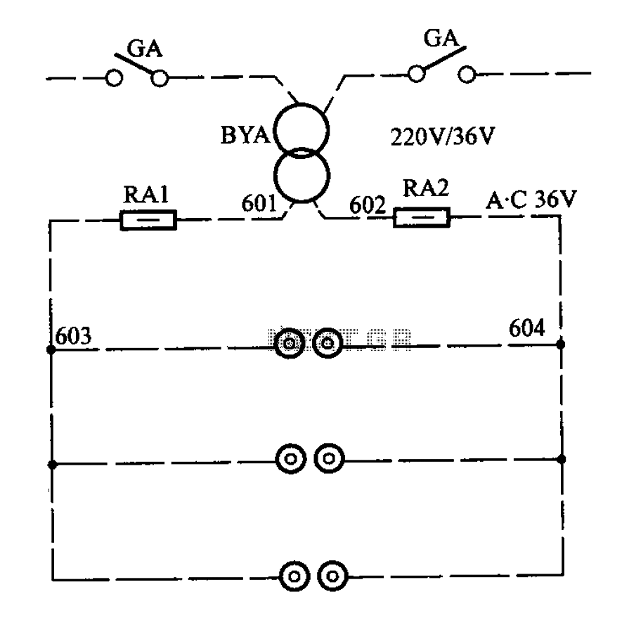
The DW16M-630 type excitation switch operates with both DC and AC power. The circuit for DC operation is illustrated in Figure 7-60, while the circuit for AC operation is shown in Figure 7-61. The BQ single-phase series motor M...
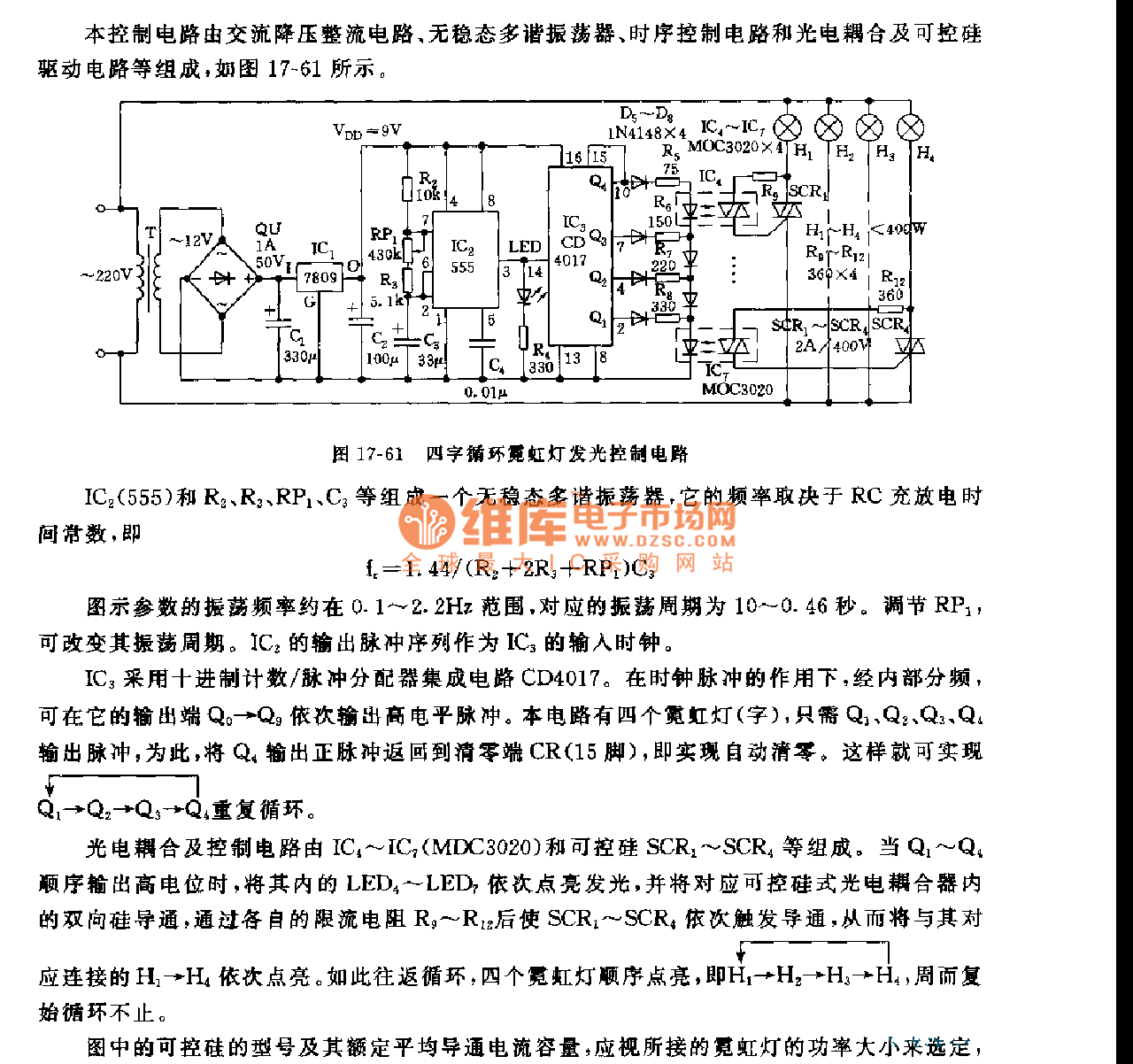
This control circuit consists of an AC step-down rectifier circuit, an astable multivibrator, a timing control circuit, an optocoupler circuit, and an SCR driving circuit, as illustrated in Figure 17-61. The astable multivibrator is formed using IC2 (555), resistors...
APM-81 lift includes the main circuit, safety circuit, and brake circuit. The APM-81 lift system is designed with a comprehensive electrical architecture that integrates a main circuit, a safety circuit, and a brake circuit, ensuring reliable operation and enhanced safety...