
PC Serial Port Receiver

The circuit operates by receiving serial data from a PC, which is transmitted through the serial port. This data is processed by the CMOS chips, which are configured as shift registers. The use of CMOS technology is advantageous due to its lower power consumption and higher noise immunity compared to traditional TTL logic.
The design includes an optical isolator to protect the PC from voltage spikes and noise that may arise from the connected lights. This isolation is crucial for maintaining the integrity of the PC's serial communication while ensuring that the control signals can safely drive the outputs.
Each of the 4 CMOS chips manages 8 outputs, allowing for a total of 32 outputs when all chips are utilized. The circuit can be expanded further by adding additional 8-bit shift registers, which can be daisy-chained to increase the number of controllable channels. This flexibility makes the circuit suitable for larger light displays.
The discrete components in the circuit may include resistors, capacitors, and diodes, which serve various functions such as signal conditioning, timing, and protection. Proper selection and arrangement of these components are essential for ensuring the reliability and performance of the circuit.
The schematic diagram (SERIAL.GIF) provides a visual representation of the circuit layout, detailing the connections between the CMOS chips, optical isolator, and the outputs to the Christmas lights. This diagram serves as a valuable reference for assembly and troubleshooting, ensuring that the circuit functions as intended in controlling the light show.This circuit was designed to control a 32 channel Christmas light show from the PC serial port. Originally designed with TTL logic, it has been simplified using CMOS circuits to reduce component count. It is a fairly simple, reliable circuit that requires only 4 common CMOS chips (for 8 outputs), an optical isolator, and a few discrete components.
The schematic diagram (SERIAL.GIF) illustrates the circuit with 16 outputs which can be expanded with additional 8 bit shift registers. 🔗 External reference
Related Circuits
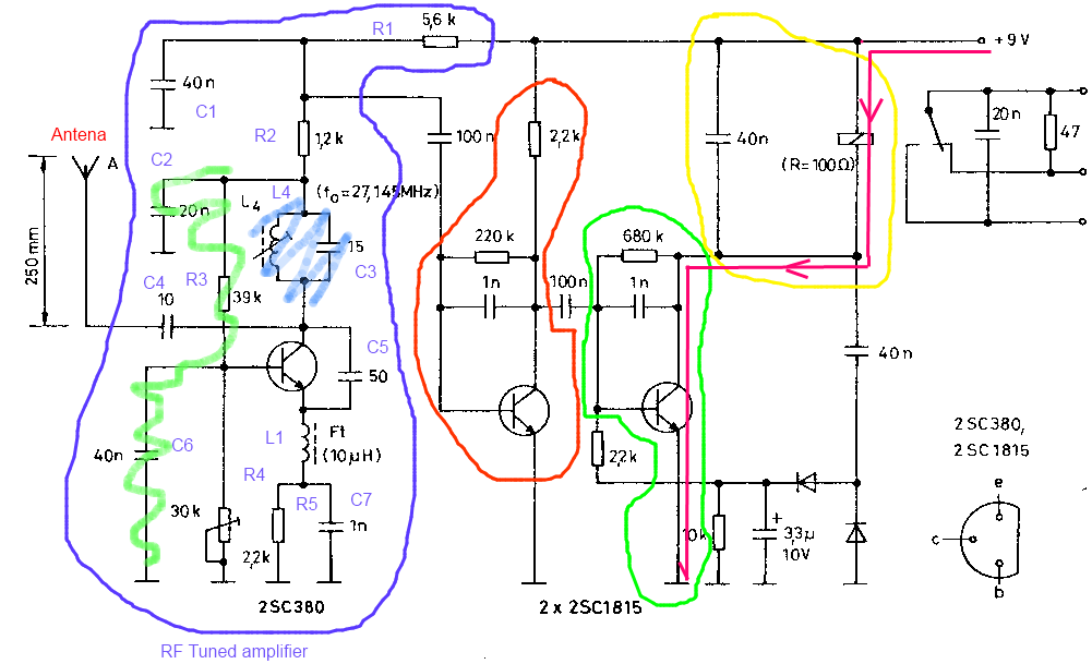
The circuit described is a toy car receiver, which operates similarly to the transmitter but in reverse and with additional filtering. The receiver is tuned to a frequency of 27.145 MHz to capture signals at this frequency. Following the...
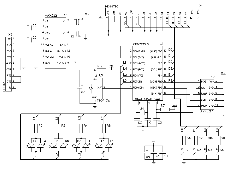
The LCD display is represented by the connector X1. It has a HD44780 compatible LCD controller and is using the 4-bit interface to send data to the LCD controller. The LEDs are multiplexed. It is possible to connect 12...
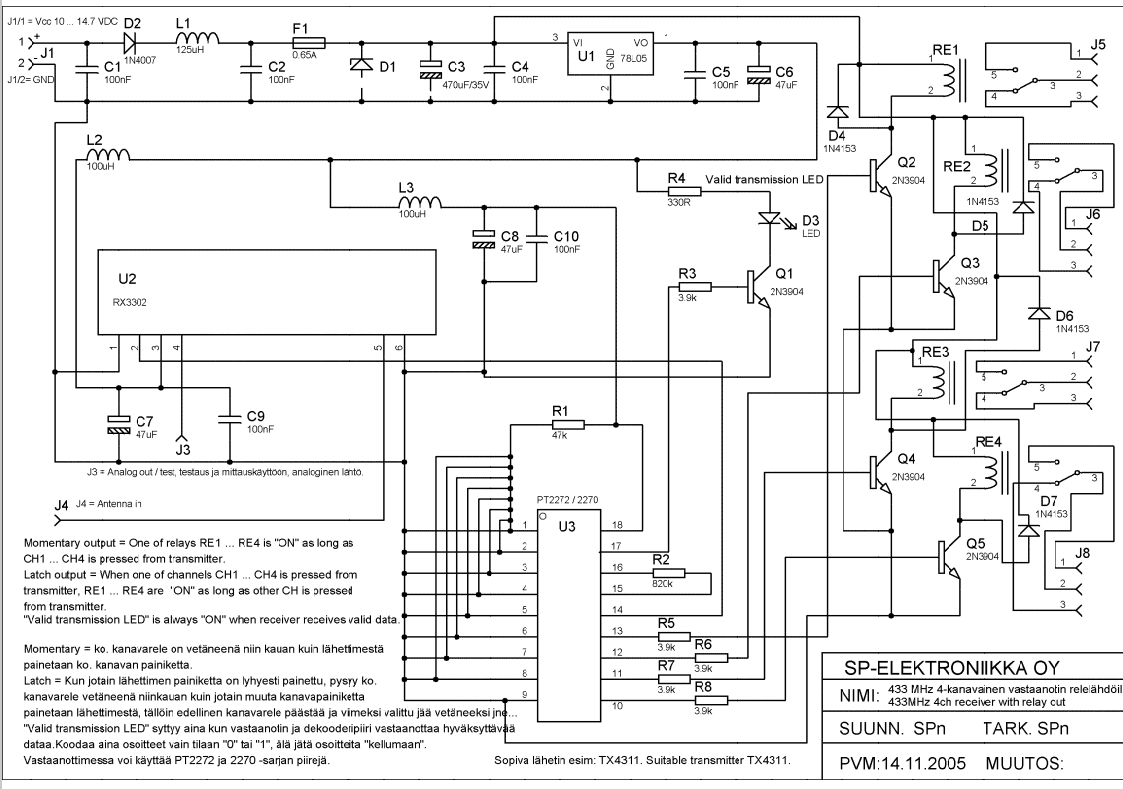
Momentary output: One of the relays RE1...RE4 is ON as long as CH1---CH4 is pressed from transmitter. Latch output: when one of channels CH1...CH4 is pressed from transmitter RE1...RE4 are ON as long as other CH is pressed from...
This is a portable, high-power incandescent electric lamp flasher. It functions as a dual flasher (alternating blinker) capable of managing two independent 230V AC loads (bulbs L1 and L2). The circuit is entirely transistorized and operates on battery power....
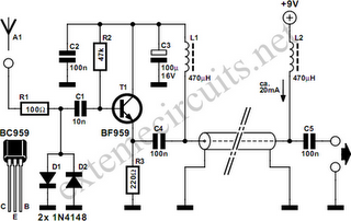
Function: step down the antenna impedance from high to 50 ohms and not, as would be expected, to effect a change from balanced to unbalanced. Component: .. In the context of antenna systems, impedance matching is crucial for maximizing power...
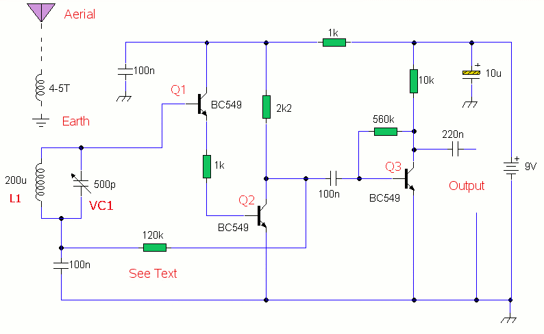
This is a compact three transistor, regenerative receiver with fixed feedback. It is similar in principle to the ZN414 radio IC which is now replaced by the MK484. The design is simple and sensitivity and selectivity of the receiver...