
AVR terminal for serial port
When a pushbutton is pressed, the terminal sends an "K", the number of the button, and a newline character. If data is received from the IR receiver, the terminal sends an "I", a hex code from the remote controller, and a newline. The protocol for the IR data is hard-coded for a Grundig remote controller. The LEDs can be turned on by sending ESC, "D", and the number of the LED. To turn them off, a lowercase "d" and the number of the LED are used (example: echo -e "\033D2" > /dev/ttyS1 turns the second LED on). Writing text to the LCD is straightforward; it can be sent directly to the serial interface (example: echo "Hello World." > /dev/ttyS1).
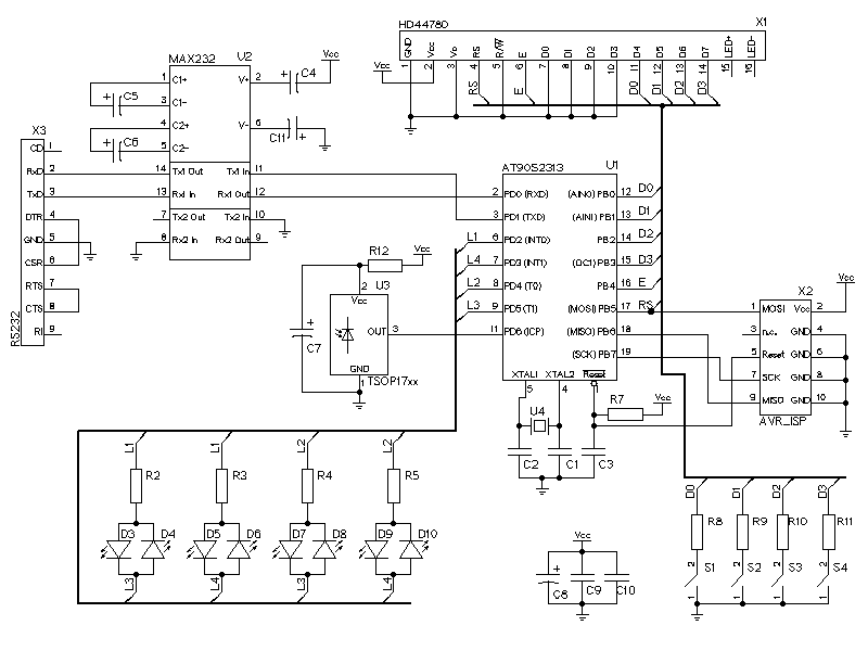
The electronic circuit described utilizes a HD44780 compatible LCD controller interfaced via a 4-bit data bus, which reduces the number of data lines required for communication. The multiplexing of LEDs allows for efficient use of available GPIO pins, enabling control of up to 12 LEDs with only 4 tristate ports. This is achieved by configuring one port as high, another as low, and setting the remaining two ports to high impedance, effectively allowing for selective activation of the LEDs.
The inclusion of the TSOP1738 infrared receiver facilitates remote control functionality, allowing commands to be sent wirelessly. The RS232 interface, implemented with a MAX232 IC, provides a reliable means of serial communication with the terminal. This interface is crucial for both sending commands to the microcontroller and receiving data from the LCD and LEDs.
The software component is developed in C, leveraging the avr-gcc compiler for building the application and avrdude for uploading the compiled code to the microcontroller. The defined communication protocols for button presses and IR commands are essential for the interactivity of the system, allowing for responsive control of the LEDs and display output on the LCD.
In summary, this circuit design effectively integrates a microcontroller with an LCD display, LED indicators, push buttons, and an IR receiver, providing a versatile platform for remote control and visual feedback. The use of standard communication protocols and well-defined interfaces ensures ease of use and expandability for future enhancements.The LCD display is represented by the connector X1. It has a HD44780 compatible LCD controller and I'm using the 4-bit interface to send data to the LCD controller. The LED's are multiplexed. I've seen the circuit somewhere in the web. It is possible to connect 12 LEDs with only 4 tristate ports with this circuit. You can address the LEDs setting 1 port high, 1 port low and 2 ports to high impedance. I've only used 8 LEDs because of space problemes in the aperture. The blue points on the photo are four push buttons. On the left side I've inserted an infrared remote receiver (TSOP1738) so that it is possible to telecontrol the computer.
Additionaly you can see the RS232 interface built with and max232 and the connector X3. Connector X2 is used for incircuit prgramming. The software is written in C. I've used the avr-gcc compiler and avrdude for programming. If you press a pushbutton the terminal sends an "K", the number of the button and a newline character. If you send something over to the IR-receiver, the terminal sends an "I", a hex code from the remote controller and a newline.
The protocol of the ir-data is hard coded for a Grundig remote controller. The LEDs can be turn on by sending ESC, "D" and the number of the LED. To turn it of use a lowercase "d" and the number of the LED. (example: echo -e "\033D2" > /dev/ttyS1 turns the second LED on) Writing text to the LCD is much easier, just send it to the serial interface. (example echo "Hello World." > /dev/ttyS1) download (c-sources and schematic) The license is public domain, so do whatever you want.
This package comes with no warranty. Source-Code and schematic: avrterminal.tar.gz Terminals build by others Have you build your own terminal based on this description? Let me know, I'd like to see a picture. 🔗 External reference
Related Circuits

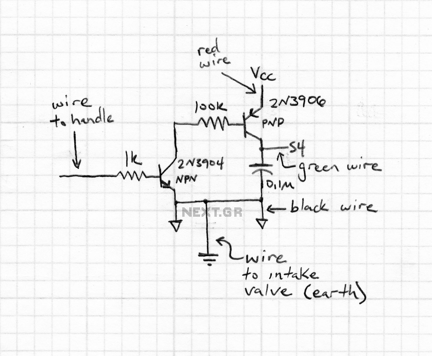
A circuit diagram for an adjustable RPM switch can be utilized to activate solenoids for auxiliary ports, VDI, shift lights, or other applications. This circuit is adapted from a rev-limiter circuit designed for rotary engines. Special acknowledgment is given...
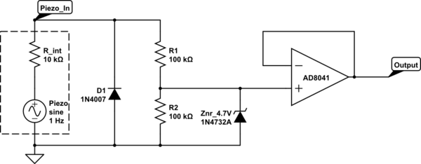
The intention is to utilize the sensor as a force sensor. It has been observed that the voltage output increases with the amount of pressure applied, although this output is only sustained for a brief period. This behavior is...
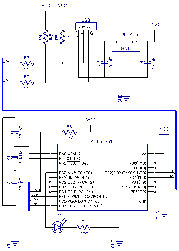
This is the second part of a USB tutorial for the ATtiny2313 microcontroller and the V-USB library. The first part covered how to derive 3.3V from USB to power circuits. In this section, the setup will be expanded with...
A basic introduction to RS232-based serial communication on the ATmega32/16 using the USART hardware. It is recommended to have the ATmega32 datasheet available for reference. Serial communication involves transmitting data one bit at a time across a communication channel,...
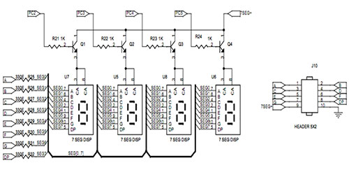
A seven-segment display is a fundamental electronic display device capable of showing digits from 0 to 9. The most prevalent configuration consists of an array of eight LEDs arranged in a specific pattern to represent these digits, typically laid...
The schematic indicates that the AccelR8 utilizes only three integrated circuits (ICs). An AVR 8515 microcontroller performs the computational tasks and manages the other circuits. A MAX603 regulates voltage and controls the power-on and power-off functions. The key component...