
signal Can someone break down how this receiver works
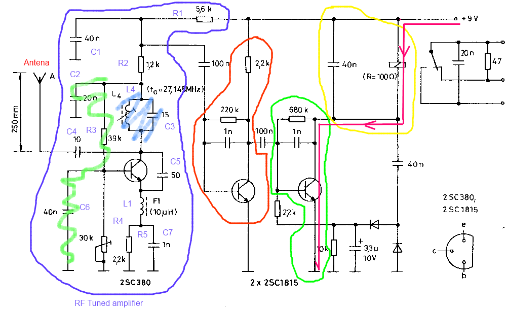
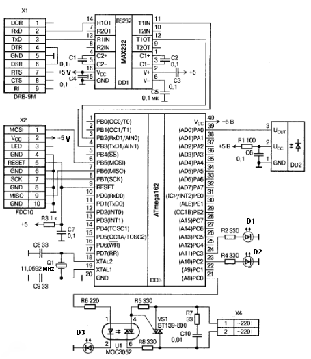
The toy car receiver circuit operates on the principle of receiving and processing radio frequency (RF) signals, specifically tuned to 27.145 MHz. The receiver's initial stage is designed to filter and amplify incoming signals, ensuring that they are strong enough for further processing. The amplification stage involves a series of transistors, capacitors, and resistors that work together to enhance the received signal while minimizing noise.
The circuit's design includes a low-pass filter formed by capacitors and resistors, which serves to stabilize the gain loop and extend the bandwidth of the transistor's response. This is crucial for maintaining signal integrity, especially in environments with various RF interferences. The use of capacitors for coupling and feedback is essential in shaping the frequency response and ensuring that the amplifier operates efficiently across its intended range.
The resonant circuit, comprised of inductors and capacitors, is critical in determining the frequency response of the amplifier. It ensures that the circuit can selectively amplify the desired frequency while attenuating others, which is vital for effective signal processing in a toy car application where precise control is necessary.
In terms of output characteristics, the circuit's DC biasing is achieved through carefully selected resistors that set the operating point of the transistors. The output voltage and current specifications indicate that the circuit is designed to drive a relay or similar load, which may not respond to rapid oscillations due to its mechanical nature. Therefore, diodes are employed to mitigate negative ringing and spiking currents that could adversely affect performance.
Overall, the toy car receiver circuit exemplifies the principles of RF design, incorporating various components to achieve reliable signal reception and processing while addressing challenges such as noise and signal integrity. The absence of certain designators in the schematic may complicate understanding, but the fundamental operation remains clear through the established relationships between the components.It is on top labled toy car receiver. The toy car transmitter is easy enough to understand, and I suspect that the receiver is essentially working the same way, but backwards and with more filtering. I have no experience in RF except that I saw this circuit before and asked someone how it works. The first stage is tuned at 27, 145 Mhz and will pickup the signal in this frequency. After that, it is all amplification and level translation or relay driving. Most of the designators are missing. I think people will have hard time explaining. abdullah kahraman Dec 15 `11 at 6:13 @abdullahkahraman I figured out the 1st and 2nd stage (sort of) already. Could you explain the 3rd part in more detail. I don`t understand what you mean by level translation. sj755 Dec 15 `11 at 6:17 I don`t know in detail, too. That`s why I commented on it. However, 680k and 2. 2k and 10k are for biasing the 3rd transistor. 100n is for coupling. 1n is to have negative feedback in high frequencies thus, reducing the gain. I don`t know what those diodes are for but one of them is probably a kickback diode. Maybe one of the diodes is to take negative feedback over lower 40n in only one direction. The upper 40n cap could be for high frequency current limiting. I am just thinking loudly, btw. That`s why this is a comment. abdullah kahraman Dec 15 `11 at 6:25 @abdullahkahraman And great comments like these is why I upvote.
You have been greatly helpful. I`d appreciate any further input. I`ll continue waiting for a complete answer though. sj755 Dec 15 `11 at 7:22 DC point is given by resistors, taking capacitors as open circuits and taking inductors as short circuits. On output dc bias is 6. 1V and collector voltage dc point is 5. 5V. Ic = 410uA aprox. Green marked network formed by C2, R3 and C6 is a low-pass filter for negative feedback. It stabilizes the gain loop and stretchs the natural bandwith of the transistor. C4 is the antenna input AC coupling. L4 and C3 build a "tank circuit" or "resonant circuit": the heart of the tuned amplifier, It gives the typical [frequency response] of this amplifier.
However, the final tuning frequency is given by the whole analysis of the stage because C5, C7, L1, and the low pass feedback filter affect AC performance too. It acts as an general purpose amplifier or coupling impedance enhancer. It is a common emitter stage with R:220k and C:1nF network acting as negative feedback and biasing base voltage level.
this is the high current sink driver. diodes network outside of the green boundary, is a no-ticking enhancer for the high frequency of the input signal. the input signal is oscillating, but relay cannot oscilate as fast as input signal. Diodes provide compensation on negative ringing, spiking currents. -output of first stage is not in colector pin, which place would give better voltage gain (maybe in that point have a great impact on output impedance ).
I think that output between R1, R2 and C1 produces poor sensitivity. 🔗 External reference
Related Circuits
The red laser line gradually sweeps across the object, which in this case is a Fabuland lamb head. Behind the scanned object, two planes positioned at a 90° angle provide a reference for the scanning software. These planes are...
The circuit consists of four light-controlled electronic switches, timing circuits, voice circuits, audio circuits, and other components. It is designed to celebrate birthdays or similar occasions, with features such as birthday candles that can be lit or extinguished. The...
An Icom PCR-1000 is utilized for listening to various MF, HF, and VHF radio stations. There is a minor inconvenience related to the antennas. The K9AY antenna performs well from 500 KHz to approximately 25 MHz, while the discone...

The circuit depicted here is designed to identify defective bulbs by capacitively sensing the electric fields they generate. To understand its operation, consider a string of bulbs with an open-circuited filament, referred to in the schematic as the String...
Various architectures of receivers have been proposed in literature, but the most popular architectures among them, such as Heterodyne, Homodyne, Wideband-IF, and Low-IF, are presented here. The Heterodyne receiver architecture utilizes two frequencies: the incoming radio frequency (RF) signal and...
An IR remote control is a widely used device found with televisions, VCRs, and home theaters. It can also be utilized to control personal devices such as lights and air conditioning. Remote controls operate using infrared (IR) light, which...