
PC SMPS PWM chip CG8010DX16

The CG8010DX16 is a highly integrated switching power supply controller designed for use in personal computer power supplies. It features a range of functionalities that enhance performance and efficiency, making it suitable for various applications. The circuit diagram typically includes multiple sections, such as the input stage, control stage, output stage, and protection mechanisms.
The input stage is responsible for rectifying and filtering the AC voltage from the mains supply. It typically employs a bridge rectifier configuration followed by a bulk capacitor to smooth the output voltage. The control stage includes the CG8010DX16 IC, which regulates the output voltage through pulse-width modulation (PWM). This IC provides feedback to ensure stable output under varying load conditions, adjusting the duty cycle of the switching signal accordingly.
The output stage generally consists of a transformer that steps down the voltage to the desired level, along with additional filtering capacitors to reduce ripple voltage. The design may also include multiple output rails to supply different voltage levels required by various components within the PC.
Protection features are crucial in power supply designs to prevent damage to both the power supply and the connected devices. Common protection mechanisms include over-voltage protection (OVP), over-current protection (OCP), and thermal shutdown. These features are integrated into the circuit to ensure safe operation under fault conditions.
Overall, the schematic of the PC Switching Power Supply using the CG8010DX16 provides a comprehensive overview of the components and their interconnections, illustrating how the power supply achieves efficient voltage regulation and protection for reliable operation in computing environments.Here are the datasheet and the circuit dram of a PC Switching Power Supply using the IC CG8010DX16.. 🔗 External reference
Related Circuits
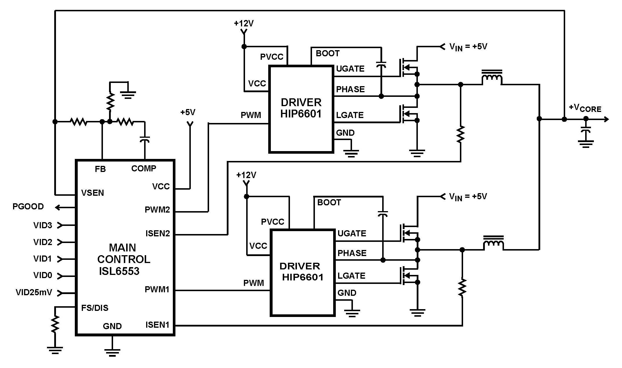
The ISL6553 multiphase PWM control IC, along with its associated gate drivers (HIP6601, HIP6602, or HIP6603), establishes a precise voltage regulation system tailored for advanced microprocessors. Multiphase power conversion represents a significant evolution from traditional single-phase converter configurations, addressing...
Most governors utilize pulse width modulation (PWM) and pulse position modulation (PPM) in their circuits. The 555 timer is commonly used in these applications. The pulse width is typically fixed at 0.5 milliseconds, which is essential for the functioning...
Pulse width modulation, commonly referred to as PWM, is utilized to regulate the power supplied to a load without sacrificing efficiency. This technique is often employed in controlling the speed of an electric motor. PWM operates by varying the width...
A guitar to MIDI interface was designed to serve as an interface between guitar playing and MIDI control of external hardware and software. This document describes the details of the design, experimentation, implementation, and final outcome of the project....
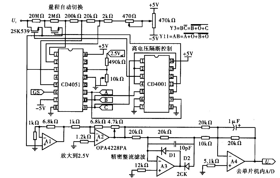
Voltage measurement is a fundamental aspect of electronic technology today, with increasing demands for accuracy and functionality in instruments. This is particularly critical when measuring signals with significant phase differences, as it is essential to ensure the accuracy of...
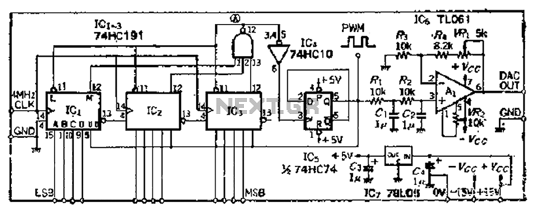
A PWM clock signal is generated at 4096 times the input frequency, counting up (Q3) until the base of ICi-IC3 is full. The output point produces a maximum clock signal. On one side, voltage data is loaded into IC3,...