
PCB Exposure Box with Countdown timer (ATMEGA8)
All components are housed in a wooden box. The box has dimensions approximately 50x30x60 cm³ and must have an extra room for hosting the countdown board and the two ballasts. The height of that room, the distance between the bottom of the box and the shelf, can be 5-8 cm. On one side of the shelf, the four starter bases will be installed, and on the other side, the four lamps along with their G13 bases.
For the lamp system, the following components are required:
- 4 x 15W Black Light UVA fluorescent lamps with a peak radiation at ~350nm, suitable for photochemical procedures. Examples include F15W/T8/BL from Sylvania and Actinic BL from Philips.
- 2 x 40W Ballasts, which are commonly used in fluorescent lamps.
- 4 x Starters that can support 15W lamps (e.g., 22W starters).
- 4 x Starter bases for mounting.
- 8 x Bases for the lamps with holes for screwing onto the wood.
- Flexible wire commonly used in fluorescent lamps.
- 20 x Screws of appropriate size for assembly.
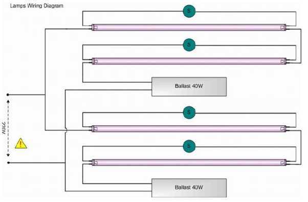
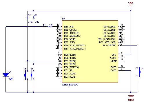
The system is designed to ensure safe operation and efficient functionality. The microcontroller is programmed to manage the countdown and control the relay that activates the lamp system. The 7-segment LED displays provide a clear visual indication of the remaining time, enhancing user experience. The physical layout of the wooden box is optimized to accommodate all components securely, while also allowing for adequate ventilation for the lamps and ballasts during operation.Four blacklight lamps, 15W each, emit radiation at the region of UVA, with a peak around 350nm where the thin surface above the copper of the photosensitive board, is... sensitive. The lamps are taken by two and are connected in series thus shaping two similar modules. Each module has its own ballast and can be connected to 220V AC via a relay. A microcontroller counts a user defined countdown and upon reaching zero activates a relay. The time remaining is displayed on four 7-segment led displays. The maximum countdown is 99 minutes and 59 secs. The desired countdown is entered using only two buttons, SET and START/STOP. Short term push of the SET button will increase the current digit while prolonged push will change the digit from secondss to decades of seconds, to minutes and so on.
Pushing once the START/STOP button, will make the MCU accept the desired countdown. Pushing the START/STOP button one more time, will start the countdown and connect the lamp system to 220V AC, via the relay. If START/STOP button is pushed again before countdown reaches zero, the lamp system will be deactivated.
When the countdown reaches zero the lamp system is deactivated and a 3 seconds beep is sounded. The timer remembers the last used countdown and uses it as default every time the system is switched on. All things above are housed in a wooden box. You can design the box by yourself however I had it done by a technician. There are 3 distinctive parts that constitute your PCB Exposure Box; the Box the Lamp System and the Counter System along with the display.
You are gonna need a wooden box with dimensions aproximately 50x30x60 cm3. The box must have an extra room for hosting the countdown board and the two ballasts. The height of that room, that is the distance between the bottom of the box and the shelf, can be 5-8 cm. On the one side of the shelf will be installed the four starter bases and on the other side the four lamps along with their G13 bases.
Here is a very detailed description on how to build your own box, upon which I relied to decide the dimensions of my box. However the final design I used is the same as Papanikolaou's box in his Darkroom Timer project. Many thanks to both of them! For the lamp system you will need: 4 x 15W Black Light UVA fluorescent lamps with a peak of radiation at ~350nm.
Those lamps are suitable for photochemical procedures and can usually be used in insect killing. Examples are F15W/T8/BL from Syllvania and Actinic BL from Phillips (approx. cost 10?/lamp) 2 x 40W Ballast. This is the common ballasts used in fluorescent lamps (approx. cost 2?/ballast) 4 x Starters that can support 15W lamps (ex 22W starters approx. cost 0.5?/starter) 4 x Starter bases (approx. cost < 0.2?/base) 8 x Bases for the lamps with holes so they can be screwed on the wood (approx. cost 0.6?/base) Wire. Prefer flexible wire which is commonly used in fluorescent lamps. 20 x Screws. Use the size you thing that best fits.I tested the schematic virtually and in real time. And by "virtually" I mean I used an Electronics Systems Simulation Software like Proteus VSM... and like nothing else (...coz as far as I know there is no competitor so far!). I am not doing any advertisement but Proteus VSM is amazing and for those who haven't heard about it yet, I recommend that they try, at least, a demo version from www.labcenter.co.uk Only after Proteus said I was right, did I try the circuit in a breadboard and that fact saved me a lot of time, especially in the code development and debugging. So saying "I tested the circuit in real time" I mean I put every component on the breadboard and there I fixed any problems that Proteus didn't find.
🔗 External reference
Related Circuits
This circuit enables observation of movement between other stroboscopes. Generation of rectangular signal is based on NE555. This circuit requires a low power supply that is made from a simple transformer TR1, traditional rectifier bridge and zener diode. NE555...
A demonstration of external interrupts in the AVR (Atmega8) microcontroller, including a circuit diagram and C code for the interrupt service routine (ISR). The Atmega8 microcontroller is a versatile device widely used in embedded systems, particularly for applications requiring external...

This is essentially a flasher circuit modified to control a bulb instead of an LED. It utilizes a 555 timer integrated circuit functioning as an astable multivibrator. The flashing rate can be adjusted from very fast to a maximum...
AT89S52 for Bell Timer Circuit Diagram. Features: 7-segment display is replaced with LCD display. DS1307, uses AT89S52 microcontroller and I2C. The circuit utilizes the AT89S52 microcontroller, which is an 8-bit microcontroller from the Atmel 8051 family. This microcontroller is programmed...
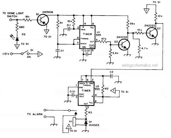
This circuit diagram represents a smart car alarm timer. This design is more advanced compared to traditional car alarm systems. When activated, the alarm remains active for 80 seconds, following an initial delay of 15 seconds. The smart car alarm...
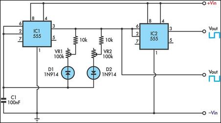
This timer utilizes two 555 integrated circuits (ICs) to adjust the desired output. The variable resistors VR1 and VR2 serve as potentiometers to modify the cycle speed. The circuit can be powered with a 9 to 12-volt power supply,...