
Variable on-off times circuit using two 555 timers
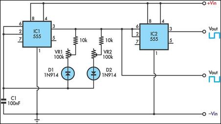
The circuit design incorporates two 555 timers configured in astable mode, allowing for continuous oscillation and providing a variable duty cycle. The use of two timers enables the generation of a more complex output waveform, which may be useful for applications requiring varying frequencies or pulse widths.
Potentiometers VR1 and VR2 are strategically placed in the timing circuit to provide adjustable resistance, thereby altering the charging and discharging times of the timing capacitors. This adjustment directly influences the frequency and duty cycle of the output signal. The output can be connected to various loads, depending on the application, such as LED drivers, sound generators, or other timing-related functions.
The power supply for this circuit should be stable, providing a voltage range from 9 to 12 volts. The current draw is minimal, typically in the range of a few milliamps, which makes this circuit suitable for battery-operated devices or low-power applications. Proper decoupling capacitors should be included near the power pins of the 555 ICs to ensure stable operation and minimize noise.
In summary, this dual 555 timer circuit offers flexibility in timing applications through adjustable cycle speeds, making it a versatile choice for various electronic projects.This timer uses two 555 ICs to Vary the desirable output. VR1 and VR2 are the potentiometers to change the speed of cycles. You can drive it with 9 to 12 volt power supply and few milliamps. 🔗 External reference
Related Circuits
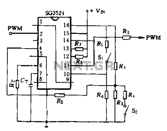
The SG3524 is utilized solely as a pulse width modulator. The error amplifier is configured in a follower arrangement. As illustrated in Figure 10-7, the ACR output connects to PWM output pin 2, which serves as the control signal....
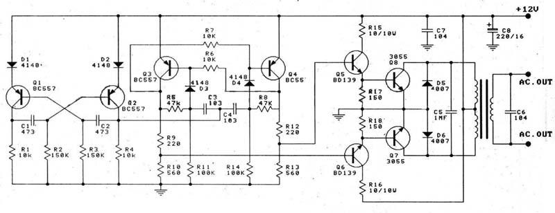
This circuit is a 100W DC inverter based on a transistored multivibrator and serves as a transistor signal amplifier. The inverter converts a 12V DC input voltage to approximately 220V AC. It is recommended to use a 12V car...
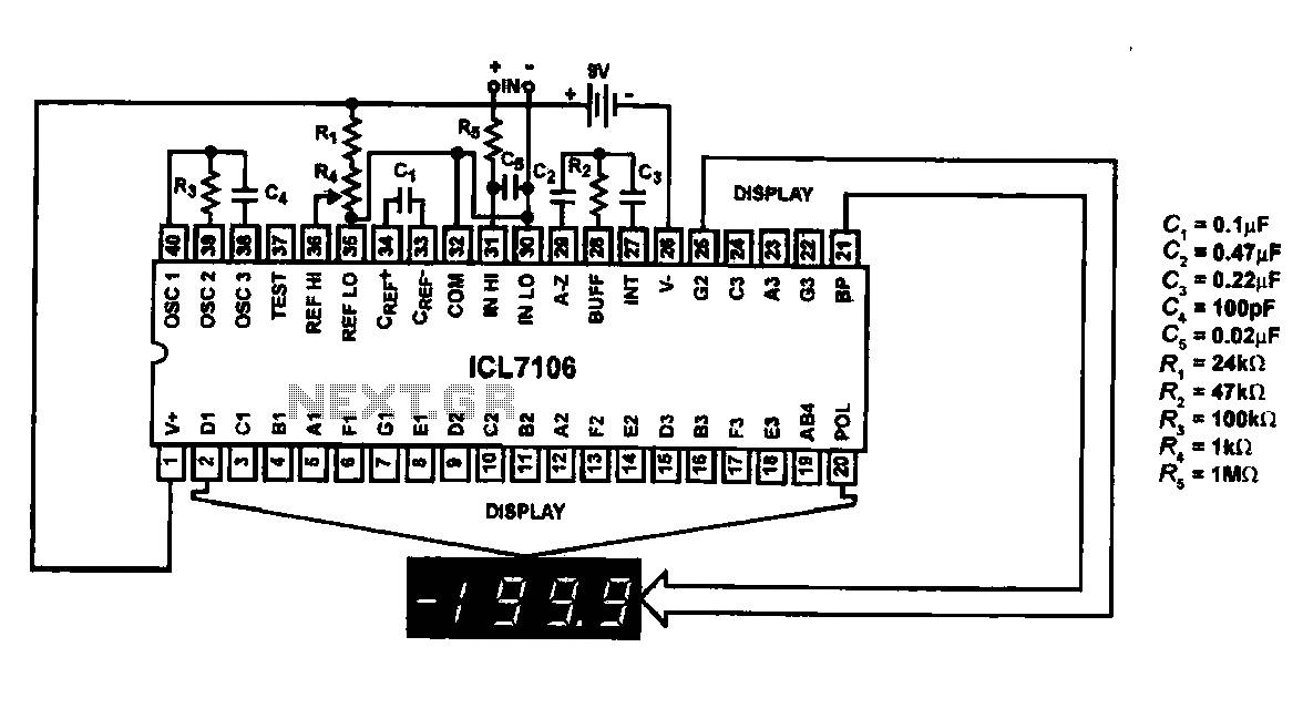
This circuit utilizes the ICL7106 / ICL7107 chip to drive a liquid crystal display (LCD). In this configuration, the ICL7106 / ICL7107 functions as a signal measurement and analog-to-digital (A/D) converter. It detects an analog input signal, amplifies it,...
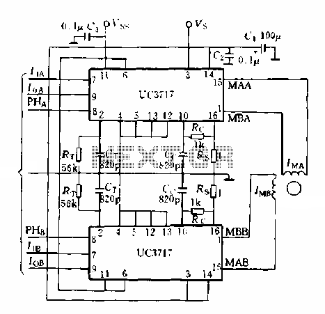
A typical application of a two-phase stepper motor is illustrated in Figure 5-15. It consists of two UC3717A components that can create a microcomputer control system for a two-phase permanent magnet or hybrid stepping motor. The control signals for...
The human eye is highly sensitive to visible light but cannot detect infrared (IR) radiation. This limitation can make it challenging to test or verify equipment that emits infrared radiation. An IR detector circuit has been developed to address...
These circuits could be used as the basis for Model Railroad DCC Boosters or PWM motor controllers. The first schematic is for a basic 3 Amp - DCC Booster using the LMD 18200 CMOS, H-Bridge. Included in the design...