
Smart Car Alarm Timer Automotive-Circuits
The smart car alarm timer circuit integrates several key components to achieve its functionality. At the core of the design is a microcontroller or timer IC, which governs the timing sequence of the alarm. Upon activation, the circuit initiates a 15-second delay, during which the system prepares for the alarm signal. This delay can be implemented using a resistor-capacitor (RC) network or programmed within a microcontroller, depending on the complexity and requirements of the design.
Once the 15 seconds elapse, the alarm is triggered, and it remains active for a total duration of 80 seconds. This is typically achieved through a relay or transistor switch that controls the power to the alarm sounder, which could be a siren or a buzzer. The choice of sounder influences the overall effectiveness of the alarm, as a louder sound can deter potential intruders more effectively.
Additionally, the circuit may include various sensors, such as motion detectors or door sensors, which can serve as triggers for the alarm. These sensors enhance the security features of the system by detecting unauthorized access or movement around the vehicle. The integration of a reset mechanism can also be beneficial; this allows the user to deactivate the alarm manually or automatically after the designated time period.
Power supply considerations are crucial for ensuring the reliability of the alarm system. The circuit should be designed to operate efficiently from the vehicle's battery, with appropriate voltage regulation to prevent damage to sensitive components. Furthermore, incorporating a backup power source, such as a capacitor or rechargeable battery, can provide additional reliability in case of power interruptions.
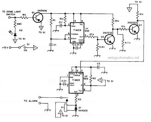
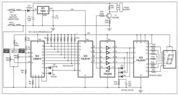
Overall, this smart car alarm timer circuit represents a significant advancement in vehicle security technology, combining efficient timing mechanisms with enhanced detection capabilities to provide a robust alarm system.This is the circuit diagram of smart car alarm timer. This circuit is clever compared to common car alarm design. When this car alarm timer circuit is activated it will make the alarm remains activated for 80 seconds. It has 15 seconds dela.. 🔗 External reference
Related Circuits
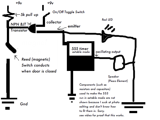
The door alarm is a compact device that activates an alarm when the door is opened. It is particularly useful for maintaining privacy, alerting individuals to the presence of others in a room while they are occupied elsewhere in...
This circuit deactivates an amplifier or any other device when a low-level audio signal at its input is absent for at least 15 minutes. By pressing P1, the device is powered on, allowing any appliance connected to SK1 to...
This is a Courtesy Light Extender for vehicles. It extends the ON time of the interior lights when a door is closed, allowing passengers to see where they are seated. The Courtesy Light Extender circuit is designed to enhance the...
A battery is a crucial component of any battery-backed system. Often, the battery is more costly than the system it supports. Therefore, it is essential to implement all practical measures to extend battery life. According to manufacturer data sheets,...
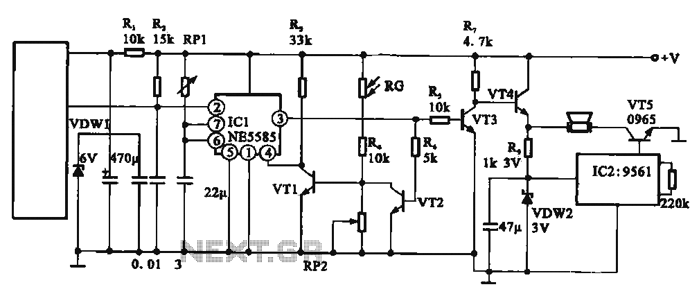
This circuit illustrates an automatic unattended burglar alarm system designed primarily for residential use, warehouses, and similar applications. The circuit features a pyroelectric infrared sensor integrated with a light control mechanism. It comprises components such as resistors (RG, RP2,...
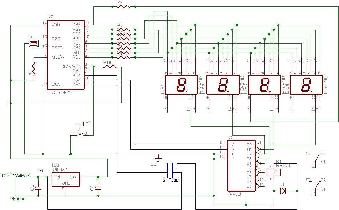
I tried to design a timer that would do everything it needed to do but with the smallest number of pieces and simplest mode of operation. It only needs the PIC, a four digit LED display, one other IC,...