
pcb fabrication Feasibility Question and Advice on CAD software
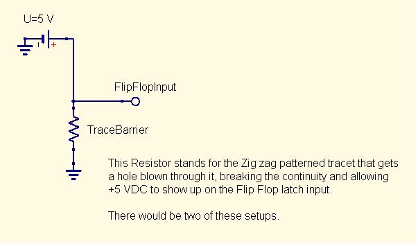
The proposed circuit design involves a physical barrier detector system that utilizes a breakable copper trace embedded in an adhesive sticker. The copper trace is arranged in a zigzag pattern to maximize coverage of the intended area while ensuring sensitivity to projectile impacts. When a projectile strikes the barrier, it disrupts the continuity of the copper trace, resulting in a voltage change that can be detected. This voltage change is designed to trigger a flip-flop circuit, which is a critical component in the gate logic for a counter-timer system.
The flip-flop will be powered by a +5VDC supply, ensuring compatibility with common digital logic levels. The output of the flip-flop can be used to increment a counter or initiate a timer, thus allowing for precise measurement of the projectile's velocity. The circuit should also include a current limiting resistor in series with the copper trace to mitigate the risk of overheating or fire, particularly in the event of a short circuit or excessive current flow.
For the manufacturing aspect, it is advisable to explore local PCB fabrication services that can accommodate custom designs, as well as inquire about the feasibility of producing adhesive-backed copper traces. In terms of CAD software, options such as KiCad or EasyEDA are recommended for their user-friendly interfaces and suitability for creating simple PCB layouts. These tools can facilitate the design process without requiring extensive experience in CAD.
In summary, this project combines innovative detection technology with practical electronics to create a reliable and efficient method for measuring projectile velocity, while also emphasizing safety and manufacturability.For a hobby project I have bread boarded, I am considering using a pair detectors that operate as a single use physical barrier. When hit by a projectile, a trace is broken allowing +5VDC to to trigger a flipflop that is part of my gate logic for a counter-timer.
I have envisioned this detector as a thin adhesive sticker with a thin copper trace e mbedded in it that forms a simple pattern to cover the area, zigzaging across the surface. Similar to the passive RF sticker tags used by retail stores for antitheft. My questions are: 1) Will it be practical to have a manufacturer print a batch of these things for me 2) I`ve never used CAD software before, is there a suggestion for a free CAD program, that doesn`t have a huge learning curve for this type of project (I`m a linux guy but thinkning W7 is more likely here ) EDIT: Photo diodes are a great idea, and I will likely try them and ask questions in a separate thread. The break-able trace allows for more configurations and keeps slew rates ( and other rates ) small. I plan to use a very small distance to track the velocity of said projectile, like 1 or 2 cm. I have a 10 Mhz clock for my timer. EDIT2: I should have added a current limiting resistor to the diagram so as not to start a fire with the trace.
but I think you get the idea from this diagram. 🔗 External reference
Related Circuits
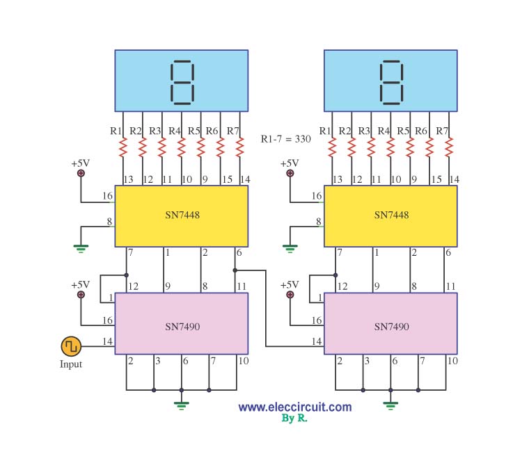
A decade counter circuit is an electronic circuit designed to perform a sequence of numerical calculations, allowing for either forward or backward counting. Forward counting refers to the circuit counting from smaller to larger numbers, while backward counting is...

A parametric equalizer on an audio-mixer-sized PCB. The circuit design features a parametric equalizer implemented on a printed circuit board (PCB) sized for integration into an audio mixer. The equalizer allows for precise control over the frequency response of an...
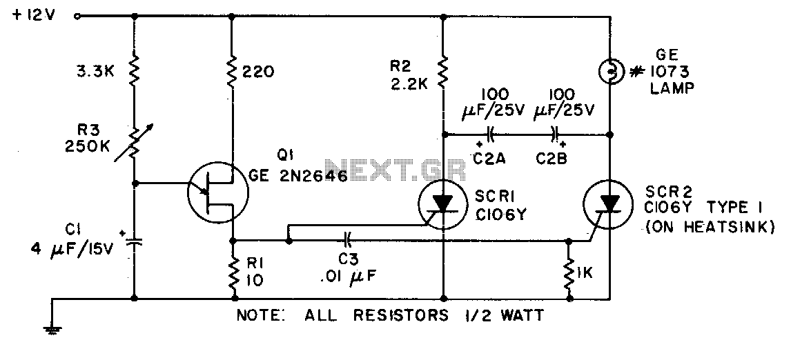
Due to its capability to handle heavy inrush currents, this incandescent lamp flasher utilizes the C106 SCR. The components illustrated allow for the flash rate to be adjusted by potentiometer R3, ranging from 36 flashes per minute to 160...

The circuit disconnects the battery from the load when the output voltage drops below a predetermined level. Capacitor C1 charges through resistor R1, activating transistor Q2. The collector current then flows through resistor R2, turning on transistor Q1, which...
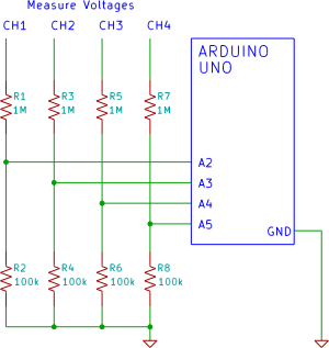
A four-channel voltmeter that displays voltage readings in a software application running on a computer. An Arduino reads the voltages and sends them to an application written in the Processing language. The described circuit comprises a four-channel voltmeter system that...

An AC to DC switching power adapter circuit with a maximum output power of 90W. The switching power supply is constructed using a high voltage power switching regulator IC, the MC33374, along with several additional components. The MC33374 IC...