
Radiation Indicator
The described radiation measurement circuit utilizes a Geiger-Muller counter to detect ionizing radiation. The circuit is powered by a standard AC supply and employs a double-voltage rectifier configuration to convert AC to DC, which is essential for powering the high-voltage components of the Geiger-Muller tube. The rectifier's output voltage is effectively managed through a voltage divider, ensuring that the Geiger-Muller counter receives the necessary 400 V for operation while maintaining the neon lamp's voltage at a safe 200 V.
The operation of the Geiger-Muller counter is based on the principle of ionization. When radiation passes through the Geiger-Muller tube, it ionizes the gas inside, allowing current to flow and activating transistor VT1. This transistor acts as a switch, controlling the neon lamp HL1. The flashing of the neon lamp serves as a visual indicator of radiation levels, with the frequency of the flashes correlating to the intensity of the detected radiation. The circuit's design also incorporates safety features, such as resistor R1, which ensures that the transistor turns off when no radiation is present, and resistor R2, which protects the transistor from excessive current.
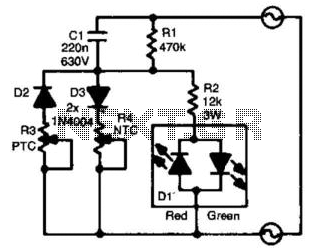
The flexibility of the circuit is highlighted by its ability to be modified for different AC voltage ratings, making it adaptable for various applications. The inclusion of additional components in the modified version for 110 volts AC demonstrates the circuit's versatility and ease of adaptation for different operating environments. Overall, this simple yet effective design provides a practical solution for radiation detection, suitable for educational purposes, hobbyist projects, or basic radiation monitoring.Measuring the radiation can be made not only with expensive factory-made instrument. The simplest device (see Figure 1), can be build if you have a counter (radiation detector) type SBM-20 or similar. The circuit is powered by a 220 volts AC 50/60Hz. The double-voltage rectifier circuit is made of diodes VD1, VD2, and capacitors C1, C2. The DC vol tage across the capacitors C1 and C2 is about 310 V on each one, so the total voltage of the rectifier is approximately 620 V. The voltage 620 V is divided by a voltage divider to the 400 V. The resistors R5 and R3 forms the voltage divider for the voltage across the capacitor C1, and the resistors R6 and R4 - for the voltage across the capacitor C2.
That is why the voltage across the resistors R3 and R4 is about 200 V. Thus, the Geiger-Muller counter BD1 (radiation detector) is powered by 400 V, while the neon lamp HL1 (an indicator) is powered only by 200 V. The neon lamp HL1 is lit only when transistor VT1 is on, and this transistor is on when the radiation ionizes the gas inside the Geiger-Mueller tube BD1.
The resistor R1 helps to switch off the transistor VT1 when there is no radiation, and the resistor R2 limits the base current of the transistor VT1 when there is the radiation. When there is no radiation sources around, the Geiger-Muller produces 20. 30 electrical pulses in one minute because of the natural background radiation. Consequently, the transistor VT1 will be open for a short time - the neon lamp HL1 flashes every 2. 3 seconds, but without strict periodicity. When the radiation levels getting higher, the neon lamp HL1 flashes more frequently. This can be verified by bringing to the counter the usual Christmas toy, covered in phosphorus. When the radiation level is very high, the neon lamp HL1 is lit continuously. The circuit can be modified for 110 volts AC 50/60Hz, as shown in figure 2. In the basic circuit has been added diodes D3, D4, capacitors C3, C5 (0. 5 F x 400V), and the values of resistors R3, R4 has been changed to 150k. 🔗 External reference
Related Circuits

Often, there is a need for an additional telephone ringer in an adjoining room to be alerted about incoming calls. For instance, if the telephone is situated in the drawing room, an extra ringer may be required in the...
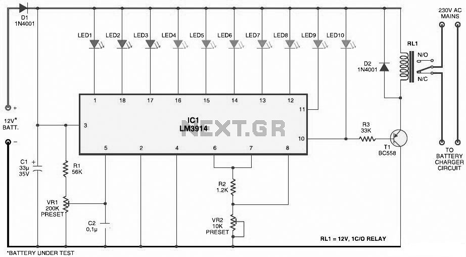
This document presents a circuit diagram for a simple and easy-to-construct battery level indicator. Typically, in mobile phones, battery levels are shown in either dot or bar format, allowing users to easily recognize the battery status. The battery level indicator...
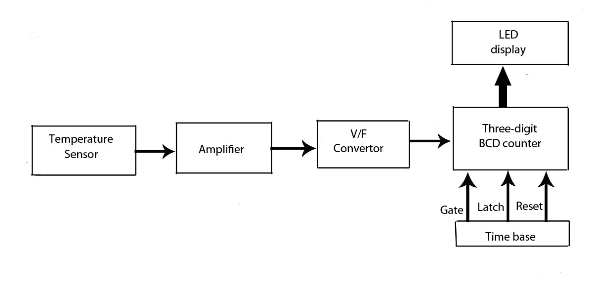
This verified project provides an idea, circuit, and operation of the LED display temperature indicator. It features a digital temperature indicator utilizing a voltage-to-frequency (V/F) converter, along with various electronic projects. The LED display temperature indicator is designed to provide a...
A charger is essential for charging a 12 Volt battery from a 12 Volt source due to the typical voltage variation between 11 Volt and 15 Volt. A battery requires a controlled charge current and voltage, which cannot be...
For the absolute measurement of temperatures, a thermometer is essential. However, in many situations, an absolute value is not required, and a relative indication suffices. It would be advantageous if a green light indicated that the temperature is within...
This circuit is designed to indicate the power output level of any audio amplifier. It is simple, portable, and displays three power levels that can be set to any desired value. For a standard HiFi stereo power amplifier, such...