
Ultra Low Power LCD Indicator
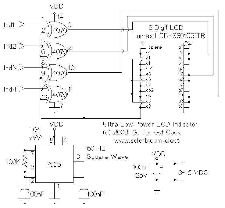
The circuit utilizes a 7555 integrated circuit, which is a CMOS variant of the 555 timer, to generate a square wave clock signal at a frequency of approximately 60 Hz. This clock signal is essential for driving the LCD display, ensuring that the visual output is dynamic and easily interpretable in various lighting conditions, particularly in full daylight. The LCD display is configured to show four bits of information, utilizing a total of 23 segments across three digits with two decimal points, thus providing a versatile platform for visual indicators.
The configuration of the display allows for multiple combinations of segment activation to represent different states or information. In the described setup, three squares and three lower segments are used to create four distinct indicators. This modular approach enables the designer to customize the visual output, potentially hard-wiring specific numbers or letters, or employing alternative LCD displays to achieve different visual effects.
The integration of four CMOS 4070 XOR gates plays a crucial role in the logic of the circuit. The output of each XOR gate is determined by the state of its inputs. When the secondary input to an XOR gate (ind*) is low, the output reflects the state of the primary input, facilitating the control of the segments displayed on the LCD. The XOR gates provide a simple yet effective means of toggling the displayed information based on the clock signal generated by the 7555 timer, thereby enabling real-time updates to the indicators as needed. This design exemplifies an efficient use of low-power components to achieve a functional and user-friendly display system.This circuit serves as an ultra-low power replacement for multiple LED on-off indicators. It also has the advantage of being easy to read in full daylight. With the parts shown, it is possible to display four bits of information. The display that I used has three digits and 2 decimal points for a total of 23 segments. Different groupings of segments can be used for the four indicators. I chose to use three squares (shown) and the three lower segments together (not shown) for the four indicators. Many other combinations could be used, one possibility would be to hard-wire numbers or letters out of each of the digits.
Other LCD displays could also be used for different effects. The 7555 IC (CMOS 555 timer) generates a square wave clock signal at approximately 60 hz. This signal is sent to the LCD backplane and the inputs of the four CMOS 4070 XOR gates. If the other input (ind*) of an XOR gate is low, the gate`s output is a 🔗 External reference
Related Circuits

The circuit utilizes a three-terminal adjustable integrated voltage regulator. It includes a gear set and a power supply voltage that is stepped down using a transformer rated at 17.5V x 2 AC. The output voltage after the bridge rectifier...
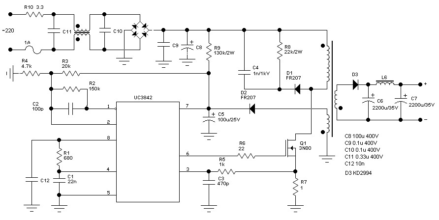
The schematic diagram originates from a 60 Watt Switching Power Supply. It details a power supply designed for a 70W stereo amplifier, utilizing the KA2S0880 chip, which encompasses all necessary components for constructing the primary section of the power...
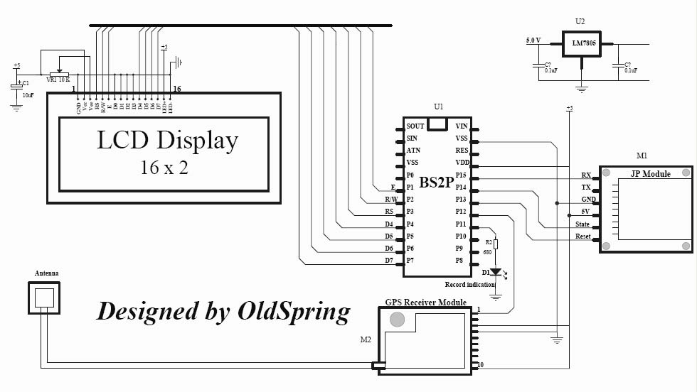
A GPS tracker demonstration program with data logging capability. It utilizes a BasicStamp 2P (or alternatively, a PIC chip) to interface with a GPS module, a JP module, and a 16x2 LCD display. The sample code employed is standard...
This line-following robot sensor, also known as a surface scanner for robots, is a compact, stamp-sized infrared proximity detector designed for short-range detection, typically within 5 to 10 mm. The line-following robot sensor operates using infrared light to detect the...
The adjustment control for the contrast of an LC-Display typically utilizes a 10-kilohm potentiometer. This arrangement functions adequately, provided that the power supply voltage remains constant. However, in situations where the power supply is variable, such as with a...
The TS2418 is a monolithic integrated circuit telephone tone ringer that utilizes a bridge diode. When paired with an appropriate transducer, it serves as a replacement for traditional electromechanical bells. This device is compatible with either a piezo transducer...