
pest repellent circuit
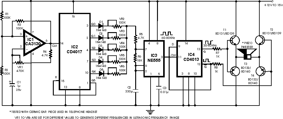
The circuit operates by utilizing a combination of several integrated circuits and passive components to generate and modulate ultrasonic frequencies effectively. The core of the design is the CA3130 op-amp configured as a low-frequency square wave oscillator, which provides clock pulses to the CD4017 decade counter. The CD4017 outputs are used to control the frequency variation by enabling different resistive presets (VR2 to VR6) connected to the NE555 timer, which is configured in astable mode. The NE555 timer generates a high-frequency signal that modulates the output frequency of the circuit.
The D-type flip-flop (CD4013) takes the output from the NE555 and divides the frequency down to a symmetrical 40 kHz signal. This is crucial for driving the piezo tweeter effectively, as the tweeter requires a specific frequency range to emit ultrasonic sound waves. The push-pull transistor configuration (T1 to T4) amplifies this signal, ensuring that the output is powerful enough to repel pests effectively.
Adjustments can be made to the circuit using the variable resistor VR1, which controls the clock pulse rate, and the presets VR2 to VR6, which allow for fine-tuning of the ultrasonic frequencies emitted. The design's flexibility in frequency modulation makes it suitable for repelling various types of pests, as different species may react to different ultrasonic frequencies. The circuit can be tailored further by increasing the number of steps in frequency variation, enhancing its effectiveness in pest control applications. The option to connect a crystal transducer directly to the output without amplification provides an alternative for applications requiring lower power consumption while still operating within the desired frequency range.It is well know that pests like rats, mice etc are repelled by ultrasonic frequency in the range of 30 kHz to 50 kHz. Human beings can't hear these high-frequency sounds. Unfortunately, all pests do not react at the same ultrasonic frequency. While some pests get repelled at 35 kHz, some others get repelled at 38 to 40 kHz. Thus to increase the effectiveness, frequency of ultrasonic oscillator has to be continuously varied between certain limits.
By using this circuit design, frequency of emission of ultrasonic sound is continuously varied step-by-step automatically. Here five steps of variation are used but the same can be extended up to 10 steps, if desired. For each clock pulse output from op-amp IC1 CA3130 (which is wired here as a low-frequency square wave oscillator), the logic 1 output of IC2 CD4017 (which is a well-known decade counter) shifts from Q0 to Q4 (or Q0 to Q9). Five presets VR2 through VR6 (one each connected at Q0 to Q4 output pins) are set for different values and connected to pin 7 of IC3 (NE555) electronically.
VR1 is used to change clock pulse rate. IC3 is wired as an astable multivibrator operating at a frequency of nearly 80 kHz. Its output is not symmetrical. IC4 is CD4013, a D-type flip-flop which delivers symmetrical 40kHz signals at its Q and Q outputs which are amplified in push-pull mode by transistors T1, T2, T3 and T4 to drive a low-cost, high-frequency piezo tweeter. For frequency adjustments, you may use an oscilloscope. It can be done by trial and error also if you do not have an oscilloscope. This pest repeller would prove to be much more effective than those published earlier because here ultrasonic frequency is automatically changed to cover different pests and the power output is also sufficiently high.
If you want low-power output in 30-50 kHz ultrasonic frequency range then the crystal transducer may be directly connected across Q and Q outputs of IC4 (transistor amplifier is not necessary). 🔗 External reference
Related Circuits
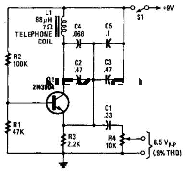
An 88 mH surplus telephone toroidal coil is utilized in a 1 kHz oscillator. It can provide up to 8 V peak-to-peak into a high-impedance load. The total harmonic distortion (THD) is 0.9%. The circuit employs an 88 mH toroidal...
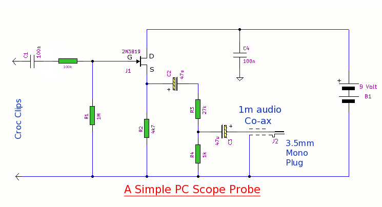
This simple PC scope probe functions as a FET follower, featuring high input impedance and low output impedance to match a microphone or line input socket on a PC or laptop. This design allows for practical examination of waveforms...
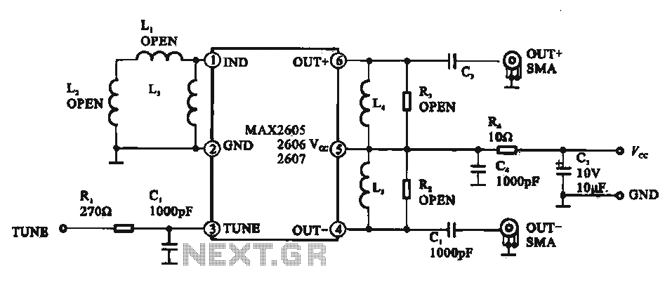
A low phase noise voltage-controlled oscillator circuit is presented, specifically integrated within the MAX2605-2609 voltage-controlled oscillator series. The circuit features a tuning voltage control terminal, allowing for adjustable oscillation frequency through a DC voltage input. The output of the...
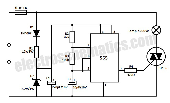
This 220V mains operated solid-state flashing lamp circuit utilizes a 555 timer integrated circuit (IC) to manage the ON and OFF durations of a triac that regulates power to the load. The circuit operates at a mains voltage of 220V,...
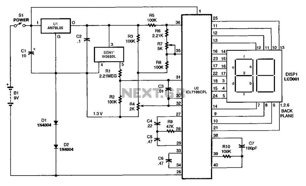
The output DC voltage of sensor SEN1 changes linearly in response to variations in relative humidity. This DC voltage is routed through resistors R1 and R2 to the analog-to-digital (A/D) converter chip U2. Resistor R4 is connected to ground,...
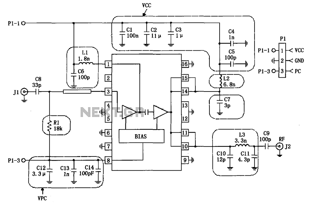
The RF2132 linear power amplifier circuit is depicted in the provided figure. A radio frequency (RF) signal enters through input pin 3 and is processed via a preamplifier. The final stage of the amplifier outputs a gain of 10....