
Relative humidity digitizer circuit diagram

The circuit incorporates a humidity sensor, SEN1, which generates a DC voltage that corresponds to the ambient humidity levels. As the humidity increases, the output voltage from SEN1 rises linearly, allowing for precise measurement. The output voltage is then fed into an A/D converter, U2, which digitizes the analog signal for further processing.
Resistors R1 and R2 serve as voltage dividers, ensuring that the voltage levels fed into the A/D converter remain within its operational range. R4, connected to ground, stabilizes the reference voltage and helps in setting the baseline for the sensor readings. This is crucial for accurate humidity measurement, as it ensures that variations in the sensor output are correctly interpreted by the A/D converter.
The digitized output from U2 is then sent to a microcontroller or processing unit, which interprets the data and drives an LCD display. Resistor R7 plays a pivotal role in this setup by potentially limiting the current to the LCD, ensuring that it operates within safe parameters. The LCD is calibrated to display humidity levels from 0 to 100 percent, providing a clear and immediate visual representation of the environmental humidity.
This circuit is particularly useful in applications such as climate control systems, weather stations, and industrial processes where monitoring humidity is essential for optimal operation. Proper selection of components and calibration of the A/D converter will enhance the accuracy and reliability of the humidity readings displayed on the LCD.A sensor SEN1 output DC voltage varies linearly according to the relative humidity. This DC voltage is supplied through R1 and R2 to the A/D converter chip U2. R4 to zero. LCD monitor by R7 reading 0 to 100 percent.
Related Circuits
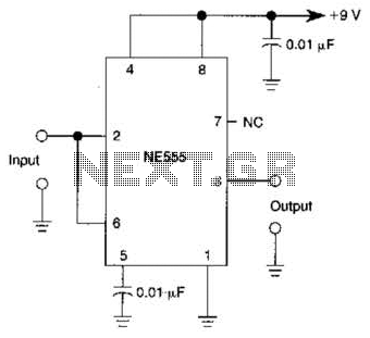
A 555 IC is configured to function as a Schmitt trigger. Inputs above and below the threshold level will turn the circuit on and off, producing a square wave output. The 555 timer integrated circuit (IC) is a versatile device...
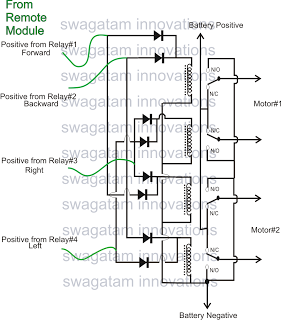
The market is filled with high-end remote-controlled toy cars; however, for hobbyists, creating one at home can be a unique experience. The following article explains how to configure a simple remote-controlled toy car using a pre-made 4-relay remote control...
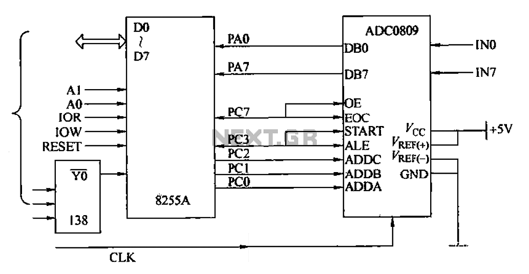
The ADC0809 is an 8-channel analog switch integrated with an 8-bit successive approximation analog-to-digital (A/D) converter. It supports the selection of eight input channels through address latch and encoder channel selection signals ADDA, ADDB, and ADDC. The address latch...
This circuit is a differential analog switch circuit utilizing the FM1208 monolithic dual differential multiplexer. It is designed for applications where the on-resistance (RDS(ON)) must match closely. The RDS(ON) for the monolithic dual multiplexer exhibits better than 1% accuracy...
The following circuit illustrates a Tachometer Circuit Project. This circuit is constructed using the 555 Timer IC. Features include a monostable IC and voltage capabilities. The Tachometer Circuit utilizes a 555 Timer configured in monostable mode to measure the rotational...

This circuit is designed as a low dropout charger using a MOSFET as the pass element; however, it does not incorporate current limiting. The circuit diagram illustrates a straightforward design. It utilizes Q3 and a Schottky diode to isolate...