
Simple high-frequency signal generator circuit diagram
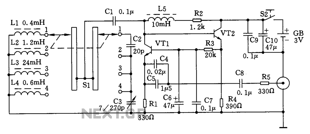
The circuit operates by utilizing an LC resonant circuit, where the inductor and capacitor values determine the oscillation frequency. The selection of the inductance through the S1 switch allows for the adjustment of the resonant frequency, enabling the generator to produce a wide range of high-frequency signals. The frequency stages are designed to cover different ranges, facilitating applications that require specific frequency outputs.
The choice of transistors VT1 and VT2 is crucial, as they must be capable of handling high frequencies with minimal distortion. The recommended transistors, such as the 9018 and C535, are well-suited for this application due to their high transition frequencies. Using 1/8W carbon film resistors ensures that the circuit maintains stability and reliability under various operating conditions.
Capacitor C5 plays a vital role in the resonant circuit, and its selection between monolithic and ceramic types allows for flexibility in component sourcing while maintaining performance. The high-frequency inductors L2, L3, L4, and L5 can be purchased or custom wound to meet specific requirements, ensuring that the generator can be tailored for various applications.
Inductor L1's construction method is essential for achieving the desired inductance and performance. The use of high-strength wire and a specific winding technique aids in minimizing losses and enhancing the quality factor of the inductor. The four-throw switch S1 enables easy selection between frequency bands, providing the user with a straightforward method to access different frequency ranges quickly.
Overall, this high-frequency signal generator is a versatile tool for generating various frequencies, suitable for testing and development in RF applications. The careful selection of components and thoughtful design ensures that it can meet the demands of high-frequency signal generation effectively. As shown for the simple high-frequency signal generator. Change the LC resonant circuit inductance with the band switch Sl, you can change the high-frequency oscillation freque ncy range. The machine can be divided into four stages:The first stage is 0.4 ~ 2MHz; The second stage is 2 ~ 10MHz; The third stage is 9 ~ 45MNz; The fourth stage is 60 ~ 110MHz. Component selection: VTl, VT2 selection fT 800MHz, 100 the NPN silicon tube, such as 9018, C535 and so on.
All with the resistance 1/8W carbon film resistors. Capacitor C5 with monolithic capacitors, ceramic capacitors can be used other. L2, L3, L4, L5 high-frequency magnetic inductors, but also their own wound. Ll with µ0.6mm high-strength wire, tightly wound flat 8 turns, bodiless wound µ7mm diameter coil. Sl pole four-throw switch with band.
Related Circuits
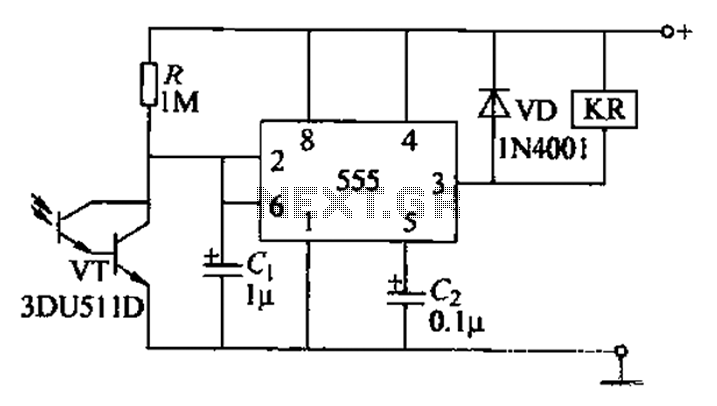
The circuit utilizes a Darlington-type phototransistor as the sensing element, which enhances sensitivity to low light levels, making it suitable for detecting reflected light signals. When the Darlington phototransistor is exposed to light, its resistance decreases, causing the voltage...
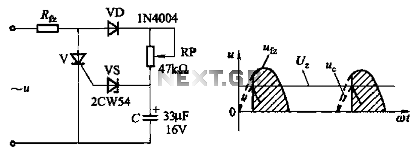
Circuit characteristics: A simple phase shift range of 180 degrees; exhibits good linearity and control accuracy compared to the first two options, making it suitable for low voltage applications, particularly in less demanding electroplating and electrolysis power supplies. The described...
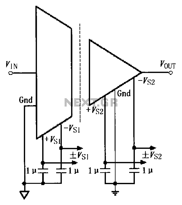
The basic connection circuit for the ISO122/124 includes power and signal connections. Each supply terminal of the ISO122/124 must be equipped with a 1 µF tantalum capacitor serving as a bypass filter. It is important to position the printed...
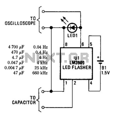
An LM3909 LED flasher functions as an oscillator, with the frequency determined by the capacitor connected to its terminals. The LED can be utilized to visually count frequency using a stopwatch for large capacitors (C > 500µF). The LM3909 is...
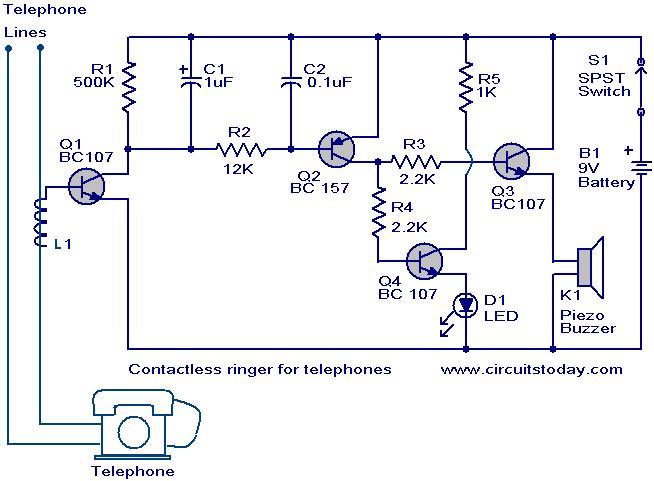
The contactless telephone ringer circuit is designed to produce an audible ring and a visual indication when a call is received. Its primary advantage lies in the absence of direct contact between the telephone line and the circuit, which...
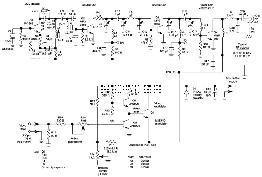
The three schematics illustrate three building blocks for a 10-meter SSB transmitter. These blocks can also be utilized independently as circuit modules for other transmitters. The VFO board incorporates an FET transmission oscillator, with the VFO signal being mixed...
Warning: include(partials/cookie-banner.php): Failed to open stream: Permission denied in /var/www/html/nextgr/view-circuit.php on line 713
Warning: include(): Failed opening 'partials/cookie-banner.php' for inclusion (include_path='.:/usr/share/php') in /var/www/html/nextgr/view-circuit.php on line 713