
Phase indicator
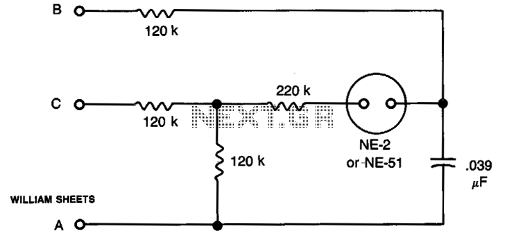
The described circuit is a phase sequence indicator designed for use with a 3-phase 120 V electrical system. It consists of three input terminals labeled A, B, and C, which connect directly to the three phases of the electrical source. The primary component of the circuit is a neon bulb, which serves as a visual indicator of the phase sequence.
In operation, when the circuit is connected to the 3-phase source, the neon bulb remains off if the phases are connected in the correct sequence (A, B, C). However, if the phases are connected incorrectly, the neon bulb will illuminate, signaling that a phase swap is necessary. This allows the user to easily identify and rectify the incorrect phase connections.
The circuit's design includes a simple mechanism for troubleshooting. If the neon bulb lights up when the phases are connected, the user can interchange any two leads (for example, A and B) to test the sequence. If the bulb turns off after the interchange, this confirms that the sequence is now correct. Conversely, if power is lost on any one of the phases, the neon bulb will also light up, serving as an important alert for maintenance or monitoring purposes.
This circuit is particularly useful in industrial and commercial settings where 3-phase systems are prevalent, providing a reliable means to ensure proper phase sequence and system functionality. The neon indicator not only enhances safety by preventing potential equipment damage due to incorrect phase connections but also aids in the efficient monitoring of electrical systems.The circuit provides a simple means of determining the succession of phases of a 3-phase 120 V source used in synchro work. Terminals A, BT and C are connected to the three terminals of the source to be checked. If the neon bulb lights, interchange any two leads; the light then extinguishes and A, B, and C indicate the correct sequence.
If power on any one line is lost, the neon bulb will light. This feature may be useful for monitoring purposes. 🔗 External reference
Related Circuits
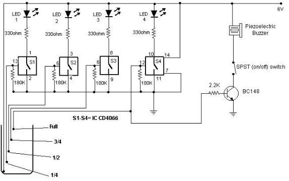
A low-cost water level indicator circuit can be designed using this schematic. This water level indicator utilizes a CMOS IC, the CD4066, to indicate the amount of water present in an overhead tank and provides an alarm when the...
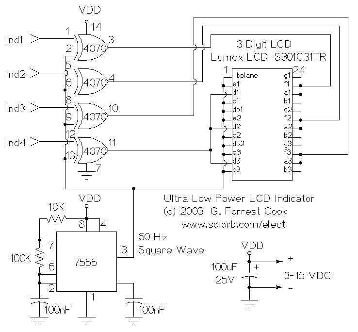
This circuit serves as an ultra-low power replacement for multiple LED on-off indicators. It also has the advantage of being easy to read in full daylight. With the parts shown, it is possible to display four bits of information....
The ISL97676 can be utilized as an LED driver capable of managing six channels of LED current for TFT displays. This driver supports the operation of up to 78 LEDs with a voltage range of 4.5V to 26V, or...
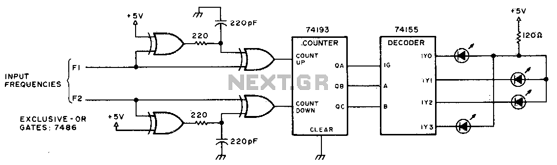
This circuit utilizes LEDs to visualize the beat frequency generated by two-tone oscillators. At any given moment, only one LED is illuminated, and the perceived rotation of the light dot accurately reflects the beat frequency. When f1 is greater...
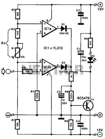
Two operational amplifiers are utilized as comparators to signal an excessive magnitude of an audio frequency (AF) signal, regardless of whether the signal is positive, negative, or asymmetrical. A reference voltage is established for both operational amplifiers using a...

This circuit is designed for lamp dimming and similar applications. It requires only one RC phase lag network. To prevent the hysteresis (or "snap-on") effect, the capacitor is reset to approximately 0 volts at the end of every positive...