
Beat frequency indicator
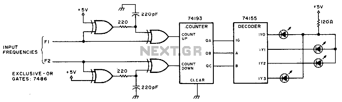
The circuit operates by employing two oscillators that generate frequencies f1 and f2. The beat frequency, which is the difference between these two frequencies, is represented by the illumination of a series of LEDs arranged in a circular pattern. The circuit can be designed using a microcontroller or discrete components such as operational amplifiers and transistors to control the LED states based on the frequency inputs.
When f1 exceeds f2, the circuit logic activates the next LED in a clockwise progression, creating the visual effect of a rotating dot. Conversely, if f1 is less than f2, the circuit activates the LEDs in a counterclockwise manner. The transition between LEDs is controlled by the timing derived from the beat frequency, ensuring a smooth rotation effect that corresponds to the frequency difference.
In the case where f1 equals f2, the circuit is designed to turn off all LEDs, resulting in no apparent rotation. This condition indicates that the oscillators are in sync, providing a clear visual feedback mechanism for users to determine the relationship between the two frequencies.
The schematic may include components such as resistors for current limiting, capacitors for filtering, and possibly a potentiometer for adjusting the frequency of one of the oscillators, allowing for fine-tuning of the beat frequency. The use of a microcontroller can simplify the design, enabling software-based control for LED sequencing and potentially allowing for additional features such as frequency display or audio output corresponding to the beat frequency.This circuit uses LEDs to display the beat frequency of two-tone oscillators. Only one LED is on at a time, and the apparent rotation of the dot is an exact indication of the best frequency When fl is greater than f2, a dot of light rotates clockwise; when fl is less than f2, the dot rotates counterclockwise; and when fl equals f2, there is no rotation. 🔗 External reference
Related Circuits
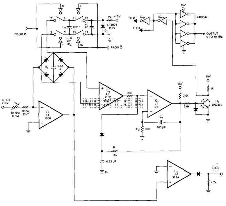
This voltage-to-frequency converter (VFC) accepts bipolar AC inputs. For -10 to +10 V inputs, the converter produces a proportional 0 to 10 kHz output. Linearity is 0.04%, and the temperature coefficient (TC) is approximately 50 ppm/°C. To understand the...
The LM3361A features a complete narrowband FM demodulation system that operates at supply voltages of less than 2V. The device includes several blocks such as an oscillator mixer, FM IF limiting amplifier, FM demodulator operational amplifier, scan control, and...
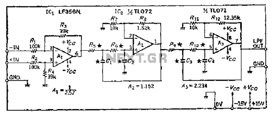
A 24 dB/octave Butterworth filter with a maximally flat characteristic is constructed using two filters, each capable of providing a 12 dB/octave response. This configuration allows for a 3 dB point adjustment. To achieve the desired cutoff frequency, adjustments...
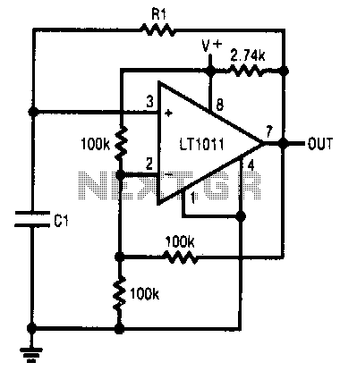
This simple RC oscillator utilizes a medium-speed comparator with hysteresis and feedback through R1 and C1 as timing elements. The frequency of oscillation is theoretically independent of the power supply voltage. Additionally, the comparator swings to the supply rails...
The preamplifier is based on the LM733 or NE592, featuring a bandwidth of 100 MHz. The FET inputs offer an input impedance of approximately 1 MΩ. Signal conditioning is achieved through the use of Q4, Q5, and IC2. The...

When the lamp turns off, a reset pulse is generated for the corresponding counter by NAND gate IC1. The counter then counts up again. The display's progression rate can be adjusted to the desired speed using potentiometer P1. Only...