
timing circuit
The timing circuit for firing a spark plug at specified intervals can be designed using a combination of a rotary encoder, a microcontroller, and a driver circuit. The rotary encoder will provide feedback on the shaft's rotation, generating a pulse for each complete revolution. This pulse can be processed by a microcontroller, which is programmed to count the pulses and determine when to activate the spark plug.
The microcontroller can be configured to trigger an output pin after counting either 10 or 20 pulses, depending on the desired timing. The output from the microcontroller can then be connected to a transistor or a relay, which will act as a driver circuit to handle the higher current required to ignite the spark plug.
The schematic would include the following components:
1. **Rotary Encoder**: This device will convert the mechanical rotation of the shaft into electrical signals. It typically outputs a series of pulses corresponding to each revolution.
2. **Microcontroller**: A suitable microcontroller (e.g., Arduino, PIC, or STM32) will be programmed to count the pulses from the rotary encoder. It will also control the timing of the spark plug firing.
3. **Driver Circuit**: A transistor (NPN or MOSFET) or a relay will be used to switch the high voltage required for the spark plug. The microcontroller output pin will connect to the base/gate of the transistor/relay.
4. **Power Supply**: A power supply capable of providing the necessary voltage and current for both the microcontroller and the spark plug circuit.
The overall circuit should also include necessary protective components such as diodes to prevent back EMF from damaging the microcontroller and capacitors for noise filtering. Proper layout and grounding techniques should be employed to ensure reliable operation and minimize interference.
This design will allow for precise control over the timing of the spark plug firing, ensuring optimal performance for the intended application.I am hoping to get some help on a timing circuit I need to build. I need to have a spark plug fire every 10 or 20 revolutions that a shaft.. 🔗 External reference
Related Circuits
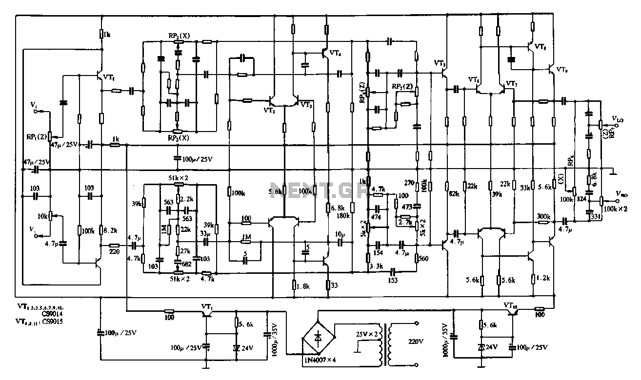
Figure 4-11 illustrates a feedback attenuator that comprises a transistor-based tone control circuit. This circuit features a conventional high and bass control system, along with balance control, volume control, loudness adjustment, and subwoofer control, as well as field sense...
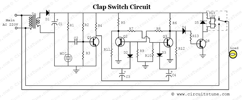
This is a simple electronic circuit for a clap switch project. It is suitable for beginner electronics learners who enjoy experimenting with new projects. The circuit can turn on or off a 220V electronic device, such as a fan...
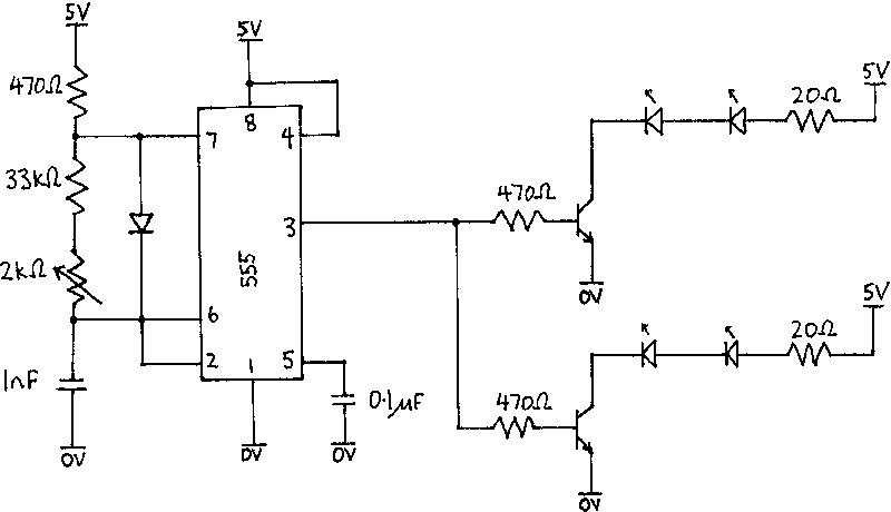
The infrared receiver requires the infrared light to be modulated at 38 kHz, which corresponds to a period of 26 µs. The specifications for the receiver suggested using a 50% duty cycle; however, this configuration did not perform as...

This smoke detector electronic project is designed using the LM1801 and common electronic components. The smoke detector circuit diagram does not utilize ionization detection, gas sensors, or optocouplers; instead, it employs two photoresistors (LDRs) and an LED. The circuit...
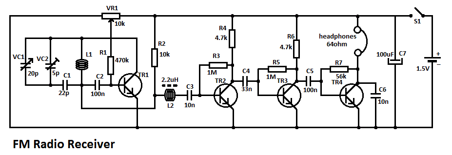
This simple FM radio receiver circuit consists of a regenerative RF stage, TR1, followed by a two or three-stage audio amplifier comprising TR2 to TR4. In some areas... This circuit is designed to receive FM radio signals, utilizing a regenerative...
A high-quality and straightforward intercom circuit utilizing only three transistors. By pressing switch S2, the circuit generates ringing signals. To create a two-way intercom, two identical circuits can be constructed and combined as illustrated in diagram 2. The circuit's...