
Timer Garage Door Circuit Schematic Diagram

The timer garage door circuit is designed to automate the opening and closing of a garage door based on a predetermined time interval. The schematic diagram illustrates the layout and connections of various electronic components that comprise the circuit.
The primary components of this circuit typically include a timer IC, such as the 555 timer, which operates in monostable or astable mode to generate the timing signal. This IC is connected to a relay module that controls the garage door motor. The relay acts as a switch that opens or closes the circuit powering the motor based on the output from the timer.
Additional components may include resistors and capacitors that set the timing intervals, as well as diodes for flyback protection across the relay coil. A power supply circuit is also integrated to provide the necessary voltage levels for the timer and relay operation.
The printed circuit board (PCB) design is crucial for ensuring proper connections and minimizing noise and interference. Careful layout of traces is essential to handle the current requirements of the motor and to ensure reliability in operation. The schematic should also include safety features, such as fuses or circuit breakers, to protect against overload conditions.
Overall, this timer garage door circuit provides a convenient solution for automated control of garage doors, enhancing both security and ease of use for the user.Timer Garage Door Circuit schematic diagram, printed circuit board 🔗 External reference
Related Circuits
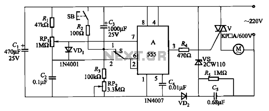
The circuit illustrated in Figure 3-12 incorporates variable speed and timing control functions. When switch S is set to position 1 and button SB is pressed, the motor initiates operation. After a predetermined delay, the motor automatically shuts down....
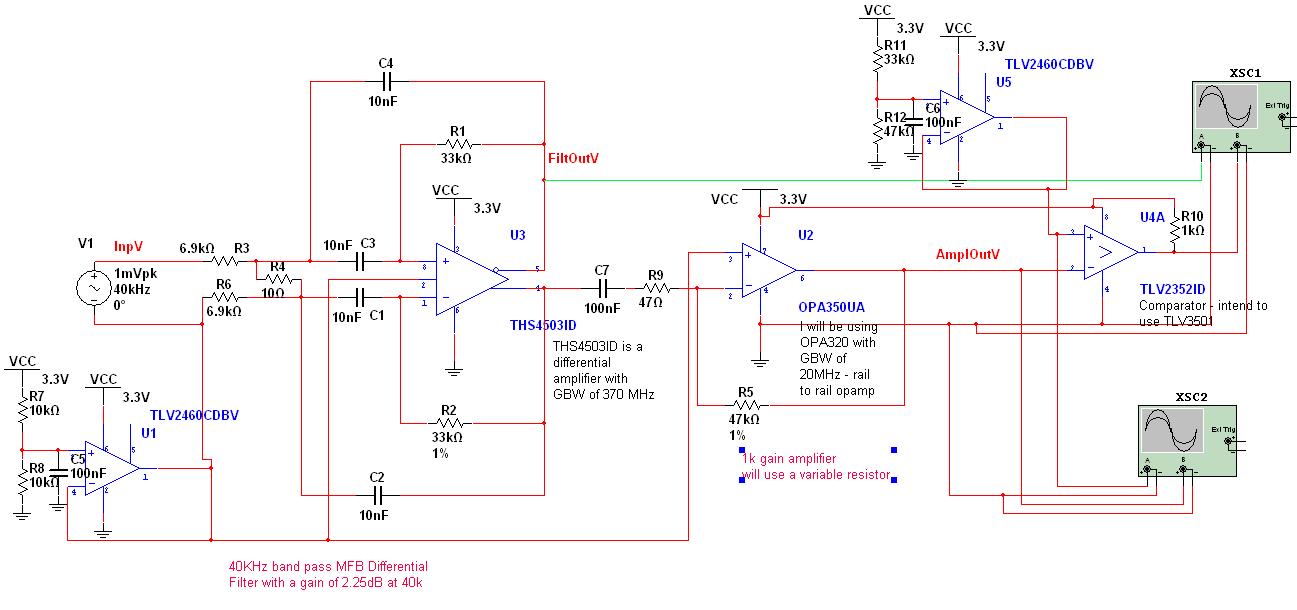
A circuit has been designed to detect the duration of an ultrasonic pulse as it travels a certain distance. The input signal is sourced from a 40 kHz ultrasonic receiver. The first stage consists of a 40 kHz band-pass...
A homemade photography LED array is being pursued, ideally configured as 6 series and 5 parallel, operating at 24 volts and 1000mA per row. Each LED row will emit a different wavelength, collectively covering the entire spectrum. The goal...
A fingerprint door lock system is being considered for implementation. The primary component is a fingerprint reader that, upon recognizing a valid fingerprint, will instruct an Arduino microcontroller to activate a locking mechanism for a predetermined duration. The locking...
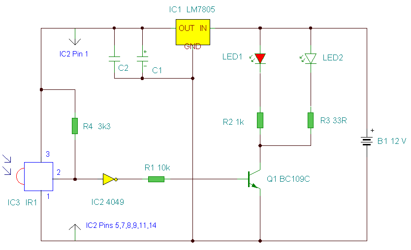
This is an improved IR remote control extender circuit. It has high noise immunity, is resistant to ambient and reflected light and has an increased range from remote control to the extender circuit of about 7 meters. It should...
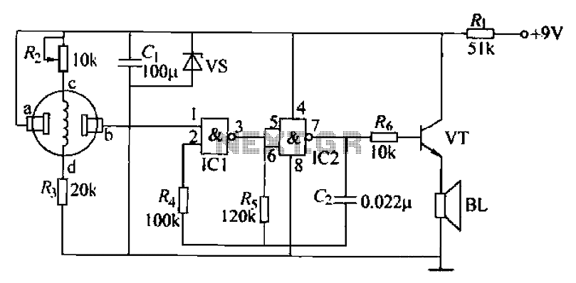
The combustible gas alarm circuit is depicted. The circuit comprises a gas sensor, a multivibrator, and audio output components. The multivibrator is implemented using two NAND gates within an integrated circuit (IC2) and includes external resistive and capacitive components....