
Phase shift oscillator
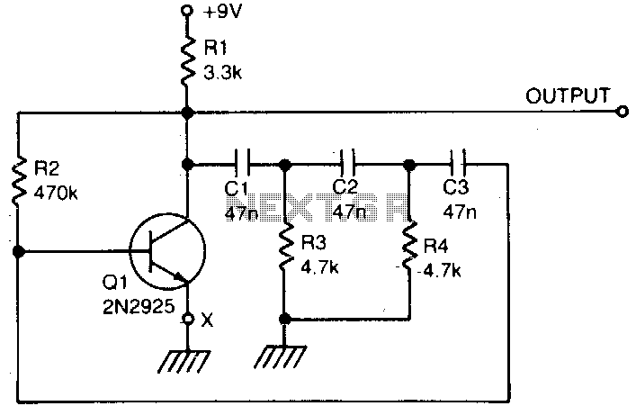
The described circuit functions as a basic phase shift oscillator, which relies on a single transistor to generate oscillations. The transistor acts as an amplifier, while the phase shift network, composed of resistors and capacitors, determines the frequency of oscillation. The distortion level of 104 indicates that the output sine wave may not be perfectly sinusoidal, which is common in simple oscillator designs.
To enhance the output waveform quality, a variable resistor of 25 ohms is connected to the emitter of the transistor Q1. This resistor allows for fine-tuning of the oscillation threshold, ensuring that the circuit remains in a state of oscillation without excessive distortion. The adjustment of this resistor is critical, as it directly influences the feedback and stability of the oscillator circuit.
The operating frequency of the oscillator can be modified through several methods. By integrating a 10 kΩ variable resistor in series with R3, the resistance can be adjusted to change the time constant of the RC network, thereby altering the frequency. Furthermore, the capacitors C1, C2, and C3 play a significant role in determining the frequency; using capacitors with a value of 100 nF will effectively halve the frequency of oscillation.
For more advanced control of the frequency, a field-effect transistor (FET) can be integrated in series with R3, allowing for voltage-controlled frequency modulation. This method provides a means of dynamically adjusting the frequency based on the input voltage. Alternatively, an LDR can be employed for optical control of the frequency, where the resistance of the LDR changes in response to light levels, thus affecting the oscillation frequency based on ambient light conditions.
Overall, this phase shift oscillator circuit demonstrates flexibility in frequency control and output quality enhancement, making it a valuable design for various applications in signal generation and waveform shaping.A single transistor makes a simple phase shift oscillator. The output is a sine wave with distortion of about 104. The sine wave purity can be increased by putting a variable resistor (25 ohms) in the emitter lead of Q1 (x). The resistor is adjusted so the circuit is only just oscillating, then the sine wave is relatively pure.
Operating frequency may be varied by putting a 10 K variable resistor in series with R3, or by changing CI, C2, and C3 Making CI, 2,-3 equal to 100 nF will halve the operating frequency Operating frequency canalsobe voltage controlled by a FET in series with R3, or optically controlled by an LDR in series with R3. 🔗 External reference
Related Circuits
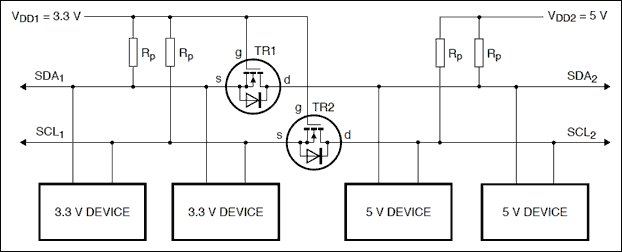
Construct a logic level shifter using discrete components such as transistors and resistors, or opt for a single-component solution with an integrated circuit (IC). Many ICs do not accept input voltages as low as 1.4 V; however, the Fairchild...
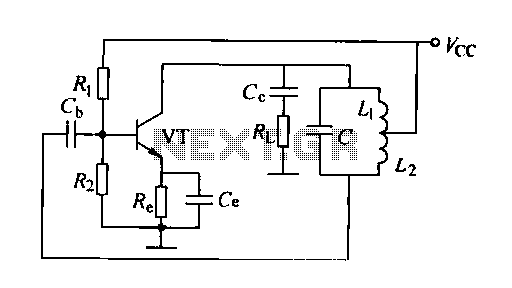
A feedback oscillator circuit utilizing inductance is presented, featuring the 3DG3 transistor. The component parameters reference values include: 1) transistors 3DG6, 2) resistances R1 at 91 kΩ, R2 at 11 kΩ, and R3 unspecified, 3) capacitance values of C...
The circuit was designed to generate an oscillator that operates at low frequencies, intended for use in electronic music production, experimentation, and testing. The low-frequency oscillator (LFO) circuit typically consists of several key components, including resistors, capacitors, and an operational...
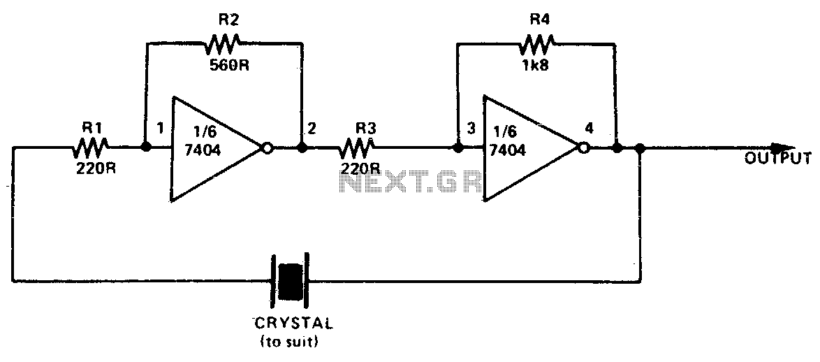
This simple and inexpensive crystal oscillator consists of one-third of a 7404 IC, four resistors, and a crystal. The inverters are biased into their linear regions by resistors R1 to R4, while the crystal provides the necessary feedback. Oscillation...

A common issue in crystal sinusoidal oscillators is the excitation of unintended modes of the quartz crystal, which diminishes the spectral purity of the oscillator. This issue is particularly significant in overtone crystals, especially for low-voltage applications. In such...
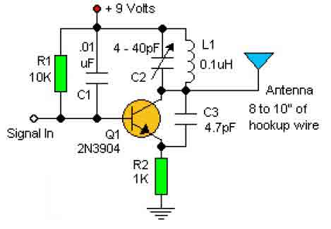
This basic RF oscillator circuit is easy to build and the components are not critical. Most of them can be found in your junk parts box. The L1 antenna coil can be made by close winding 8 to 10...